Open Nav

Mixed assembly combining Surface Mount Technology (SMT) and Through-hole Technology (THT) components on a single PCB presents unique manufacturing challenges that require specialized expertise and process optimization. Many electronic products require both fine-pitch SMT components for dense digital circuits and robust through-hole parts for connectors, Power Components, and mechanical attachments. Chinese Pcb Assembly manufacturers have developed advanced capabilities for handling mixed-technology boards, offering cost-effective solutions for complex assemblies. This article explains the mixed assembly process, addresses common challenges, and provides guidance for successfully implementing SMT-THT combination boards with China Manufacturing partners.
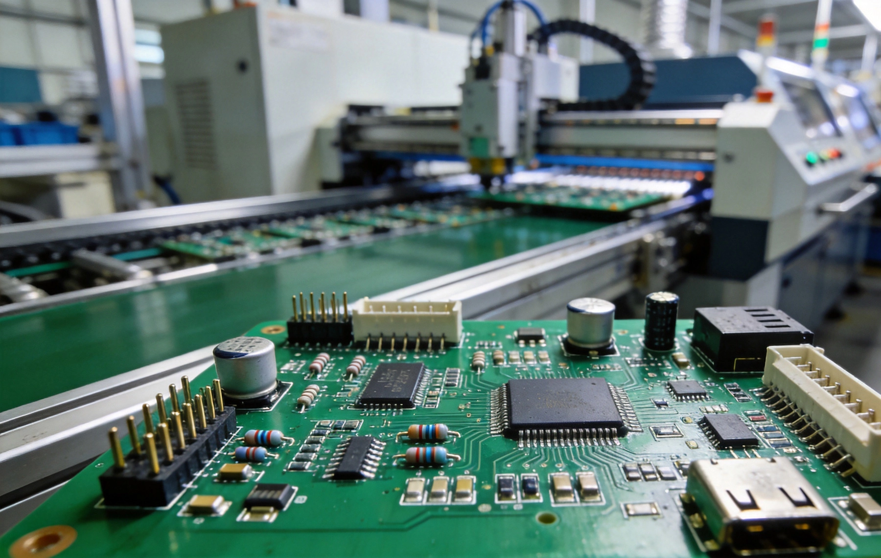
Mixed assembly becomes necessary when product requirements demand both component types within single electronic systems. SMT excels at high-density digital circuits where size minimization matters, while THT provides superior mechanical integrity for components subject to physical stress. Connectors requiring frequent mating cycles, heavy components that SMT pads cannot support, and components needing visual inspection access all favor through-hole construction. Industrial controls, Automotive Electronics, and power supplies commonly employ mixed assembly strategies.
The manufacturing sequence for mixed boards requires careful planning to ensure process compatibility. Standard practice places Smt Assembly first, with Reflow Soldering securing Surface Mount components before through-hole processing. Following SMT reflow, through-hole components insert into plated holes and receive solder—either through Wave Soldering or selective Hand Soldering depending on board complexity and component sensitivity. This sequence prevents SMT components from experiencing temperatures beyond their rated limits during Wave Soldering.
Component Placement sequencing within SMT processing affects through-hole accessibility and solder quality. Components requiring wave soldering access must remain uncovered during that process, meaning tall components should not shade through-hole areas from solder wave contact. Board designers specify component keep-out zones that manufacturing engineers use when creating assembly programs, ensuring placement decisions support subsequent wave soldering operations.
Effective mixed assembly begins with comprehensive process planning that addresses technical requirements across both component types. Manufacturing engineers review bill of materials to categorize components by process assignment, identifying which parts mount using SMT versus THT methods. This categorization determines assembly sequences, tooling requirements, and quality control checkpoints essential for successful production.
Panel design for mixed assemblies considers wave soldering accessibility alongside SMT placement optimization. Panelization strategies must provide wave contact for through-hole areas while maintaining SMT placement efficiency. Mouse bite or V-score panel separations require consideration of wave solder pot accessibility, with some designs requiring tab-routing that separates into individual boards before wave soldering rather than after.
Process flow documentation ensures consistent execution across production runs. Detailed work instructions specify component insertion sequences, solder paste requirements, and Reflow Profile parameters for each board type. Quality checkpoints at critical process transitions catch issues before they propagate through subsequent operations. Chinese manufacturers with mature process documentation systems maintain consistency across engineering teams and shift changes.
Smt Assembly for mixed boards follows standard Surface Mount procedures with additional considerations for subsequent through-hole processing. Solder paste application using stencils—typically 100-150µm thickness for standard applications—deposits solder on pad surfaces for reflow attachment. Paste inspection using Aoi systems verifies deposit volumes and identifies defects before reflow, preventing problems that would require expensive rework after wave soldering.
Component Placement utilizes high-speed SMT pick-and-place equipment achieving placement rates exceeding 30,000 components per hour. Modern placement systems handle packages from large connectors to 01005 passive resistors, with vision systems ensuring accurate positioning for fine-pitch devices. Through-hole components designated for manual insertion may be placed during SMT processing and left unconnected, or placed later depending on assembly flow decisions.
Reflow Soldering melts solder paste to create metallurgical bonds between components and pads. Temperature profiles typically ramp to 235-260°C peak depending on solder alloy and component requirements, with time above liquidus (TAL) maintained between 40-90 seconds for reliable joint formation. Convection reflow ovens with multiple heating zones enable precise profile control essential for boards with thermal mass variations from mixed component types.
Wave soldering represents the standard method for Through-hole Assembly on mixed boards, with boards passing over a fountain of molten solder that wicks into plated holes and creates fillet connections on component leads. Wave solder machines include spray nozzle systems for precise solder application, conveyor mechanisms that control board contact with waves, and preheat zones that bring assemblies to appropriate temperatures for solder wetting.
Selective soldering machines provide alternative processing for boards with temperature-sensitive SMT components that cannot withstand full wave exposure. Selective systems solder individual through-hole pins or small groups of pins using mini-wave or iron-tip methods. This capability proves essential for boards with mixed technologies where adjacent components cannot survive wave soldering temperatures. Chinese manufacturers increasingly invest in selective soldering capability to handle complex mixed assemblies.
Hand Soldering remains necessary for certain through-hole components regardless of automated processing. Connectors requiring specific orientation, components with heat-sensitive internal structures, and repair operations all require skilled hand soldering techniques. China Assembly facilities maintain trained hand soldering personnel certified to Ipc Standards, ensuring consistent quality for manual operations.
Thermal Management during wave soldering presents the primary challenge for mixed assemblies. Components already attached through SMT reflow must survive wave soldering temperatures without degradation or detachment. Components rated for single reflow may fail when exposed to wave temperatures, requiring either lower-temperature wave solder processes or process modifications that protect sensitive components.
Flux management becomes more complex when combining technologies. Residues from wave soldering flux may contaminate SMT areas, requiring thorough cleaning to prevent reliability issues. No-clean fluxes reduce cleaning requirements but may leave residues incompatible with Conformal Coating or other post-assembly processes. Process engineers must balance flux activity, cleanliness requirements, and downstream process compatibility when selecting flux systems.
Through-hole fill and solder wetting quality require careful process control. Plated through-hole barrels must achieve adequate solder fill to ensure reliable electrical connections, particularly for boards subject to vibration or thermal cycling. Insufficient hole fill creates reliability risks that may not manifest until field deployment, making process qualification essential for demanding applications.
Designers should consider manufacturing implications early in product development to avoid costly revisions. Through-hole component placement relative to SMT components determines wave solder accessibility—tall components near through-hole areas may block solder wave contact with holes behind them. Liberal spacing between component types simplifies manufacturing and improves first-pass yields.
Component selection affects mixed assembly feasibility. Some components marketed as through-hole actually mount using SMT processes with different termination styles—j-leads, gull wings, or castellated edges. Clarifying component mounting method during design prevents Bom confusion that delays manufacturing. Designers benefit from reviewing manufacturer documentation specifying recommended mounting technology for each component.
Thermal consideration during design prevents manufacturing complications. Components sensitive to multiple thermal exposures require process planning that minimizes exposure count or reduces exposure temperatures. Thermal reliefs around through-hole pads facilitate solder flow while reducing heat transfer to temperature-sensitive areas. Designers specifying thermal relief geometries based on connector and component requirements simplify manufacturing process development.
Board thickness selection affects wave solder compatibility and through-hole reliability. Standard thicknesses of 1.2-1.6mm work well with most wave solder processes, while thinner boards may warp during wave contact and thicker boards may not achieve adequate hole fill. Boards with high layer counts and corresponding thickness may require modified wave parameters to achieve reliable solder joints throughout the stack.
Via placement near through-hole components requires attention to solder flow paths. Tented or plugged vias prevent solder from wicking away from through-hole pad areas, ensuring adequate solder remains for joint formation. Via placement in wave contact zones may draw solder away from intended joints, creating insufficient solder conditions that require hand solder touch-up.
Test point accessibility for in-circuit testing affects both design and manufacturing planning. Through-hole test points provide reliable electrical access for production testing, while SMT test points may not survive wave soldering. Design for testability ensures adequate test point coverage without compromising manufacturing process flow.
Inspection strategies for mixed assemblies combine techniques appropriate for both component types. Aoi systems examine SMT solder joints and component placement, while visual inspection addresses through-hole connections. X-ray Inspection becomes valuable for boards with BGAs or other hidden joint components, revealing solder connections that visual inspection cannot access.
Through-hole Solder Joint Inspection relies on visual criteria established by Ipc Standards. Ipc-a-610 specifies acceptance criteria for different solder joint configurations, including fillet formation, surface appearance, and hole fill percentage visible from board surfaces. Inspectors undergo training and certification to ensure consistent application of acceptance criteria across production runs.
Electrical testing verifies assembly functionality beyond visual inspection. In-circuit testing (ICT) checks individual component values and circuit connectivity, identifying opens, shorts, and component value errors. Functional testing validates overall board operation, confirming that assemblies perform specified functions under load conditions.
Chinese Pcb Assembly manufacturers have developed extensive experience with mixed-technology boards across diverse application sectors. Industrial Electronics, automotive modules, and consumer products requiring both connector interfaces and dense digital circuitry flow through China facilities daily. This high volume builds process expertise that enables consistent quality across complex mixed assemblies.
Investment in versatile equipment supports mixed assembly requirements. China facilities commonly operate both high-volume SMT lines with multiple placement heads and selective soldering systems for complex through-hole processing. Wave solder machines with precise temperature and conveyor controls handle standard through-hole requirements while selective systems address challenging configurations. This equipment combination enables handling virtually any mixed assembly complexity.
Cost competitiveness in China derives from efficient process flows and economies of scale rather than quality compromises. Mixed assemblies requiring multiple process steps incur higher manufacturing costs than single-technology boards, but China labor costs and equipment utilization efficiency keep total costs competitive with alternatives. Volume throughput across diverse board types amortizes equipment investments efficiently.
Chinese manufacturers have optimized mixed assembly through process engineering investments that reduce cycle times and improve yields. Fixture designs that position boards optimally for each process maximize efficiency while ensuring quality. Preheating strategies for wave soldering reduce thermal shock while achieving adequate temperatures for solder wetting.
Statistical process control (SPC) monitoring of critical parameters enables proactive quality management. Wave solder temperature, conveyor speed, and flux application rates receive continuous monitoring with control charts identifying trends before specification violations occur. This data-driven approach reduces defect rates and improves first-pass yields.
Continuous Improvement programs identify and implement process enhancements based on production learning. When defect patterns emerge, cross-functional teams analyze root causes and implement corrective actions. Documented lessons learned inform future production runs, progressively improving process capability across the facility.
Successful mixed assembly projects with China manufacturers require clear communication and comprehensive documentation. Design files including Gerber Files, pick-and-place data, and bill of materials should specify component mounting methods unambiguously. Manufacturing partners benefit from early engagement during design phases when manufacturing feedback can influence design decisions.
Sample builds validate manufacturing processes before production commitment. Professional manufacturers produce prototypes or first articles that demonstrate process capability and identify issues requiring resolution. These samples undergo full inspection and testing, with results informing process adjustments before production scales to volume levels.
Ongoing production management maintains quality consistency across deliveries. Regular quality reviews, defect trend analysis, and corrective action follow-up ensure manufacturers meet quality requirements throughout production runs. Communication channels for addressing issues quickly prevent quality problems from escalating.
Comprehensive documentation prevents miscommunication that leads to quality issues. Bom files should clearly indicate component mounting methods for each part, distinguishing SMT versus through-hole assignments. Assembly drawings specifying component locations, orientations, and special requirements complement BOM information.
Test specifications define acceptance criteria for electrical testing performed during production. These specifications should cover test equipment calibration requirements, test point accessibility, and pass/fail criteria for each measurement. AOI and X-ray Inspection specifications if required should accompany test documentation.
Packaging and shipping requirements ensure products arrive in acceptable condition. ESD-sensitive boards require appropriate protective packaging, while boards with protruding components need foam or tray packaging that prevents damage during transit. Shipping method specifications should match product sensitivity to transit conditions.
Mixed assembly costs depend on board complexity, component counts, and process requirements. Simplifying designs by reducing component variety and standardizing on fewer part packages reduces setup costs that spread across smaller production quantities. Designers should evaluate component selection trade-offs between cost and functionality.
Panel efficiency affects per-board costs significantly. Designs that utilize panel space efficiently reduce waste and lower manufacturing costs. Manufacturing partners can suggest panelization options that maximize utilization while maintaining process compatibility, often identifying opportunities invisible to designers unfamiliar with panel processing.
Component sourcing optimization through manufacturer purchasing leverage reduces material costs. Manufacturers aggregating component purchases across multiple customers achieve better pricing than individual buyers can obtain. Turnkey Assembly services including component sourcing often cost less than Component Procurement plus assembly separately.
Industrial control systems frequently employ mixed assembly to combine digital processing circuits with power switching and connector interfaces. PLC modules, motor drives, and sensor interfaces all require robust through-hole connectors while housing complex digital electronics on dense SMT circuits. China manufacturers serve this market segment extensively.
Automotive Electronics combine high-density control circuits with power management and connector requirements. Engine control units, dashboard displays, and safety systems all require mixed assembly approaches. Automotive Quality requirements including Iatf 16949 certification add complexity that experienced manufacturers manage through robust quality systems.
Consumer products with connector requirements and power sections benefit from mixed assembly despite primarily digital content. Products including set-top boxes, home appliances, and audio equipment need external connections plus internal digital processing. Cost-competitive China Manufacturing makes mixed assembly economical for these high-volume products.
Component technology evolution continues influencing mixed assembly practices. New package types including QFN, LGA, and wafer-level chips reduce through-hole requirements by providing surface-mount alternatives for functions previously requiring through-hole packages. Designers increasingly specify all-SMT implementations that eliminate wave soldering requirements.
Automation advances enable handling increasingly complex mixed assemblies with reduced labor content. Collaborative robots (cobots) assist with component insertion and board handling, improving throughput while maintaining flexibility. Automated Optical Inspection and X-ray systems reduce reliance on manual inspection while improving detection capability.
Sustainability considerations drive process changes including lead-free conversions and reduced cleaning requirements. China manufacturers lead adoption of environmentally responsible processes including no-clean flux systems and water-based cleaning alternatives. These changes require process optimization but reduce environmental impact.
Mixed assembly combining SMT and THT components on single PCBs enables product designs that leverage advantages of both technologies. Through-hole components provide mechanical robustness and accessibility that surface mount cannot match, while SMT enables high-density digital circuitry that through-hole cannot achieve. Successful implementation requires careful process planning, appropriate equipment capabilities, and quality control strategies addressing both component types.
China Pcb Assembly manufacturers offer compelling value for mixed assembly production, combining extensive experience across diverse applications with cost-competitive pricing. Their investment in versatile equipment, process expertise, and quality systems enables handling virtually any mixed assembly challenge. Working with qualified partners during design phases ensures manufacturability considerations inform design decisions.
As component technologies evolve and new package types emerge, mixed assembly practices will continue adapting. Designers should stay current with component options and manufacturing capabilities to optimize product architectures for both functionality and manufacturability. The combination of thoughtful design and capable manufacturing partners creates products that meet performance requirements while achieving cost targets that enable market success.
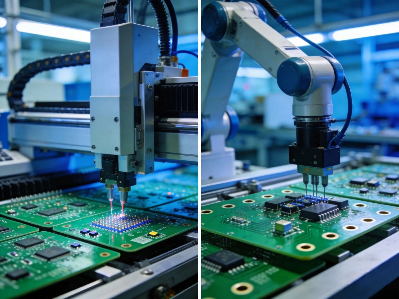
SMT vs THT PCB Assembly in China: Which Technology is Right for Your Project?June/08/2026
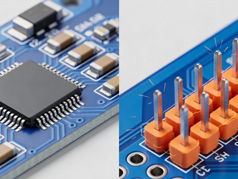
Understanding the Mechanical Strength Differences: SMT vs THT Assembly in ChinaJuly/27/2026
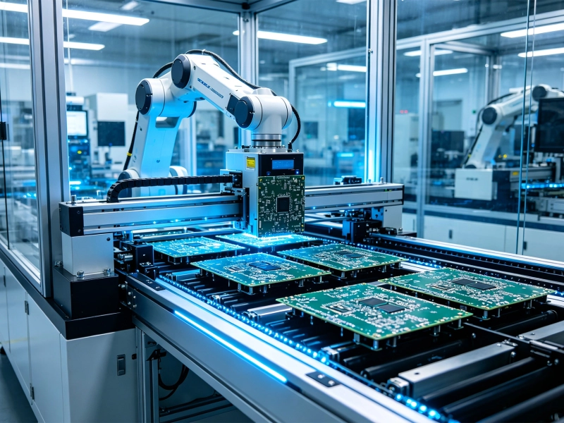
Automation Capabilities: Why SMT Assembly Wins Over THT for Mass Production in ChinaSeptember/10/2026
Cost Comparison: SMT vs THT PCB Assembly Services in ChinaJuly/07/2026
How to Choose the Best Assembly Method for Your PCB Prototype in ChinaOctober/12/2026
Which Technology is Right for Your Project?May/29/2026
The Evolution of Electronics in China: From THT to High-Density SMT PCB AssemblyAugust/06/2026

The Pros and Cons of SMT and THT in China's Electronics Manufacturing LandscapeJune/25/2026