Open Nav

The debate between Surface Mount Technology and Through-hole Technology is as old as the technology itself, yet it remains genuinely relevant in 2026. While SMT has dominated the Electronics Manufacturing landscape for decades, Through-hole Technology never disappeared—it retreated to applications where its mechanical advantages are irreplaceable. Understanding when each technology's mechanical strengths matter, and how China-based EMS providers approach both assembly methods, helps product designers, hardware engineers, and procurement teams make better sourcing decisions.
This article examines the mechanical strength characteristics of SMT and THT assemblies, explains why mechanical strength matters for different applications, and provides practical guidance for choosing between technologies. Whether you're evaluating manufacturing options in China or working with a domestic EMS provider, understanding these differences helps you design products that perform reliably in their intended environments.
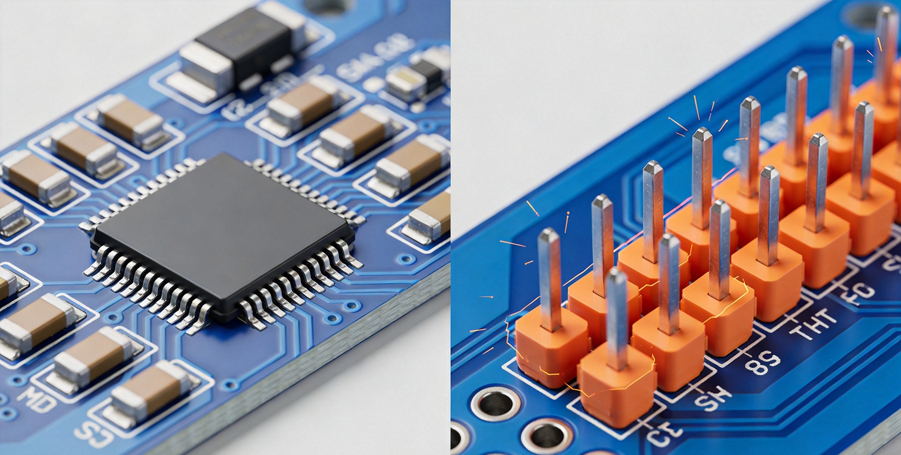
The mechanical distinction between SMT and THT begins at the most basic level: how components attach to the board. Through-hole components feature leads that pass through holes drilled in the PCB, creating a three-dimensional interlock between the component and the board. Solder fills the annular space around the lead, creating a joint that holds the component through mechanical engagement as much as metallurgical bonding. The lead, the barrel plating, the solder, and the board substrate all share the mechanical load.
Surface Mount components, by contrast, attach to pads on the board surface without any penetration through the board. The joint relies entirely on solder wetting between the component termination and the pad, with the component body held by the surface tension of the solder and, in some cases, adhesive underfill. The mechanical connection is fundamentally two-dimensional, relying on the solder joint to resist forces in all directions without the benefit of mechanical entrapment.
This foundational difference explains most of the mechanical performance differences between the technologies. THT joints resist pull-out forces, vibration, and mechanical shock through their three-dimensional interlock. SMT joints resist these forces through solder joint geometry and strength. When designed correctly, both technologies can meet demanding mechanical requirements—but the design constraints and failure modes differ substantially.
The geometry of solder joints determines how effectively they distribute mechanical loads. THT joints typically feature a barrel shape—the plated through-hole—with solder filling the annular gap between the lead and the barrel wall. This geometry creates a large solder volume relative to the lead cross-section, distributing pull-out and shear loads across a substantial joint area. The solder fillet that forms on the component side of the board provides additional mechanical engagement, increasing the effective joint height and further distributing loads.
SMT joints take various shapes depending on component type and solder process. Chip components feature fillets between the termination and the pad that resist peel and shear forces. Gull-wing leads on ICs create solder fillets that resist shear and torsion. J-lead packages trap solder within the J-shaped termination, providing mechanical retention that resembles THT interlock. Ball Grid Array packages rely on the entire solder ball joint, distributing loads across the full pad array rather than individual termination points.
Modern SMT joint design achieves remarkable mechanical performance through optimized geometry. The JEDEC standards for component handling, mounting, and solder joint geometry provide baseline requirements that enable reliable Smt Assembly. With appropriate design—adequate pad dimensions, proper solder paste deposition, and controlled reflow profiles—SMT joints routinely meet or exceed the mechanical requirements of applications ranging from Consumer Electronics to automotive under-hood environments.
Environments with sustained vibration or intermittent mechanical shock test the mechanical robustness of assembly technology. Military, aerospace, industrial, and automotive applications frequently face these conditions, and the choice between SMT and THT often determines whether assemblies survive their intended service life.
Through-hole technology excels in high-vibration environments because of the mechanical interlock between the component lead and the board. The lead passing through the board creates a shear-loaded joint where the solder fillet on both sides of the board resists vibration-induced motion. The barrel plating, embedded in the board substrate, provides additional mechanical retention that prevents lead movement even if the solder joint cracks. This inherent robustness makes THT the technology of choice for applications subject to sustained vibration—military avionics, industrial motor controls, and automotive electrical systems.
SMT assemblies in vibration environments require deliberate design to achieve equivalent robustness. The most effective strategies include maximizing solder joint volume and fillet height, using corner staking or underfill for packages with high center of mass, and selecting component packages with inherently robust terminations. QFP and QFN packages with multiple terminations distribute vibration loads across many joints, reducing the load on any individual joint. BGAs, despite their reduced lead count, achieve vibration robustness through the distributed load across the entire array.
China-based EMS providers have developed extensive expertise in vibration-resistant Smt Assembly for industrial and automotive applications. The engineering teams at leading Chinese assembly facilities understand the specific design modifications required for vibration environments—corner fillet enhancement, adhesive underfill application, and process controls that ensure consistent solder joint geometry. Working with experienced manufacturers in China for vibration-critical applications ensures that the design optimizations required for SMT reliability are properly implemented.
Portable electronics and handheld devices face a different mechanical challenge: occasional severe drop shocks that impose high transient accelerations on the assembly. A smartphone dropped on concrete experiences deceleration forces that translate to substantial inertial loads on every component. The mechanical response of SMT versus THT joints under these conditions differs significantly.
SMT assemblies often outperform THT in drop shock because the smaller mass of Surface Mount components creates lower inertial loads. A through-hole connector with heavy metal housing generates far greater force when decelerated than an equivalent surface mount component. The solder joint must resist this force proportional to the component mass, so lighter components impose lower loads on their joints. This mass advantage explains why portable electronics have universally adopted SMT—despite the perceived fragility of surface mount joints, the lower component mass results in better drop survival.
Board-level drop performance depends on the entire assembly, not just individual joints. Flexible printed circuits, underfill materials, and adhesive staking all contribute to how well the assembly survives drops. Modern smartphones and tablets undergo extensive drop testing with design modifications aimed at surviving drops from specific heights onto specific surfaces. The engineering investment required for drop survival underscores that mechanical performance isn't determined by assembly technology alone—it's the result of comprehensive design for the intended mechanical environment.
Temperature changes induce mechanical stress on solder joints through the thermal expansion mismatch between component materials and the PCB substrate. As the assembly temperature changes, the component and board expand and contract at different rates, loading the solder joint in shear. Over thousands of thermal cycles, this cyclic loading causes fatigue—microcracks that grow with each cycle until the joint fails electrically or mechanically. Understanding thermal fatigue is essential for applications subject to temperature cycling.
The Coffin-Manson relationship quantifies the relationship between thermal cycle amplitude, cycle count, and fatigue life. Larger temperature swings cause more severe fatigue damage per cycle. Higher temperatures accelerate the fatigue process. The key insight is that fatigue damage accumulates even when joints don't fail immediately—joints that survive testing may still have accumulated fatigue damage that reduces their service life.
SMT joints often demonstrate superior thermal cycling performance compared to THT joints in some conditions. The smaller joint volumes of SMT create shorter creep distances, allowing the joint to accommodate thermal expansion mismatch through plastic deformation rather than crack propagation. Additionally, SMT allows the use of flexible circuits and strain-relief design that reduces thermal stress on individual joints. For applications with moderate thermal cycling requirements, properly designed SMT assemblies provide adequate fatigue resistance without the mechanical complexity of THT.
THT joints provide superior thermal cycling performance in the most demanding conditions. The larger solder volume and three-dimensional joint geometry create greater fatigue reserves. The barrel-plated through-hole, with solder fillets on both sides of the board, distributes thermal fatigue damage across a larger volume, extending the cycles-to-failure compared to SMT joints of similar solder volume. For applications requiring thousands of thermal cycles to failure—automotive engine compartment electronics, outdoor telecommunications equipment—THT often provides the reliability margin that SMT cannot achieve.
Solder alloy selection significantly affects mechanical performance in both SMT and THT assemblies. Tin-lead solders, with their low elastic modulus and good ductility, accommodate thermal stress through plastic deformation rather than crack propagation. The transition to lead-free solders—driven by RoHS regulations—changed the mechanical performance equation, as lead-free alloys like SAC305 (96.5% tin, 3% silver, 0.5% copper) exhibit higher yield strength and lower ductility than tin-lead.
The higher strength of lead-free solders provides initial mechanical robustness but reduces the ability to accommodate thermal mismatch through plastic deformation. This shifts the fatigue failure mode from ductile plastic deformation to brittle crack propagation. The result: lead-free joints may survive initial thermal cycles better but fail more suddenly once cracks begin propagating. Tin-lead joints, by contrast, deform plastically, creating visible evidence of fatigue before complete failure.
China's EMS industry has adapted extensively to Lead-free Assembly requirements. The process controls, equipment settings, and design guidelines developed over the past two decades enable reliable Lead-free Assembly that meets or exceeds the reliability of traditional tin-lead processes. For applications where lead-free compliance is required, Chinese manufacturers have the process maturity to deliver assemblies that perform reliably in demanding mechanical environments.
Despite SMT's dominance in most applications, certain use cases genuinely favor through-hole technology for mechanical reasons. Understanding these applications helps designers avoid the error of assuming SMT fits everywhere.
Power electronics carrying significant current—typically above 5-10 A continuously—benefit from the mechanical robustness of through-hole connections. The barrel-plated through-hole provides multiple current-carrying paths: the component lead, the barrel plating, and the solder fillet all share the current load. The mechanical interlock prevents the thermal cycling-induced relaxation that can degrade SMT joints carrying high current. Large connectors, power transistors, and bus bars typically use through-hole terminations specifically for the mechanical and electrical robustness this provides.
The Thermal Management advantages of THT for high current are equally important. Through-hole components can be mounted on heavy copper substrates or attached to heat sinks with mechanical fasteners that provide thermal paths independent of the solder joint. This redundancy—where the mechanical and thermal connection doesn't depend entirely on the solder joint—provides reliability that SMT cannot match for the highest current applications.
Connectors and components subject to repeated mating cycles—like test equipment connectors, battery contacts, and module headers—require mechanical robustness that accommodates wear over hundreds or thousands of cycles. Through-hole mounting provides the mechanical retention that prevents the connector body from rocking or shifting during mating cycles. The solder joint in THT mounting distributes insertion and withdrawal forces into the board, preventing the localized stress concentrations that would crack SMT joints under repeated mechanical loading.
SMT connectors designed for reduced insertion force configurations can handle moderate mating cycles, but the most demanding applications—military connectors rated for thousands of mate/unmate cycles, or industrial equipment subject to frequent field servicing—almost universally use through-hole mounting. The mechanical advantage of THT for these applications outweighs the density and cost advantages of SMT.
Applications in harsh environments—off-highway vehicles, marine electronics, mining equipment, and oilfield instrumentation—face mechanical challenges that exceed typical commercial requirements. Vibration, shock, thermal cycling, and sometimes corrosive environments combine to stress assemblies far beyond commercial conditions. The mechanical margins built into THT construction often prove necessary for reliable service in these environments.
China-based EMS providers serving the industrial and automotive markets have developed specialized processes for harsh-environment assemblies. Conformal Coating application, edge sealing, and robust connector integration are standard capabilities at manufacturers serving these markets. The combination of THT mechanical robustness and appropriate environmental protection enables assemblies that survive decades of service in conditions that would quickly destroy commercially-rated electronics.
The mechanical advantages of SMT are equally clear in applications where THT's strengths aren't required and its limitations matter.
The lightweight, compact nature of portable electronics benefits directly from SMT's size and weight advantages. Smaller components and tighter spacing reduce board area and thickness, enabling the slim form factors that consumers expect. The reduced mass of surface mount components improves drop survival, as described earlier. Combined, these mechanical advantages make SMT the enabling technology for modern portable devices.
High-speed digital systems with thousands of interconnections—network equipment, computing platforms, and data center hardware—require the interconnection density that only SMT can provide. BGAs with hundreds of connections, fine-pitch QFPs with connections on 0.4mm pitch, and 01005 passive components enable routing densities that through-hole technology cannot approach. The mechanical performance of these assemblies, while different from THT, is more than adequate for the controlled-environment service these products typically encounter.
For applications where mechanical environments are benign—office equipment, consumer appliances, and commercial electronics—SMT's manufacturing cost advantages typically outweigh any mechanical considerations. The lower component costs, higher assembly throughput, and reduced board area of SMT assembly translate directly to lower unit costs. When the mechanical environment doesn't require THT's robustness, choosing SMT provides better value without meaningful reliability risk.
Most real-world assemblies incorporate both SMT and THT components, leveraging each technology's strengths where appropriate. A typical industrial control board might use SMT for the digital circuitry while employing through-hole connectors, through-hole electrolytic capacitors, and through-hole heavy-current inductors where mechanical robustness is needed.
Mixed-technology assembly presents process challenges that pure-SMT or pure-Tht Assembly avoids. The assembly sequence must place and solder SMT components before through-hole components, typically through reflow followed by selective soldering or Wave Soldering. The thermal mass of through-hole components affects Reflow Profile design; components near through-hole barrels may experience different thermal histories than components in clear areas of the board.
China's EMS providers have extensive experience with mixed-technology assemblies. The process engineering expertise developed over decades of serving diverse markets enables Chinese manufacturers to handle mixed-technology boards with the same efficiency as single-technology assemblies. For products requiring both SMT density and THT mechanical robustness, Chinese manufacturers provide the combination of capability, experience, and cost-effectiveness that makes this approach viable.
Whether using SMT, THT, or both, designing for mechanical performance requires attention to specific factors that determine assembly reliability.
Optimize pad dimensions for the specific component and solder process. Pads that are too small produce weak fillets; pads that are too large prevent proper solder wetting and can cause tombstoning. Follow Ipc-7351 land pattern standards as a starting point, then adjust based on manufacturer feedback and testing. For critical joints, larger-than-standard pads provide additional mechanical margin.
Minimize thermal mismatch through symmetric design. Asymmetric pad sizes or placement cause uneven heating during reflow, creating residual stress in the joint after solidification. Symmetric designs—equal pad sizes on opposing sides of a component, balanced thermal mass across the board—reduce residual stress and improve thermal cycling performance.
Consider underfill for critical applications. Epoxy underfill beneath BGA and large QFN packages dramatically improves thermal cycling and drop shock performance by bonding the component to the board substrate. The underfill redistributes thermal mismatch strain across a larger area, reducing stress on individual solder joints. The additional process step is justified for applications where mechanical reliability is critical.
Ensure adequate hole size relative to lead diameter. The annular ring—the difference between hole diameter and lead diameter—should be sufficient to allow solder to flow freely while maintaining adequate copper barrel for mechanical retention. Ipc Standards recommend minimum annular ring dimensions based on product class; for high-reliability applications, exceeding these minimums provides additional margin.
Support high-profile components mechanically. Large electrolytic capacitors, heavy transformers, and tall connectors create mechanical moment arms that stress solder joints under vibration. Mechanical support—standoff mounting, adhesive stakes, or structural brackets—reduces the load on solder joints. The investment in mechanical support typically costs less than the rework or field failure that unsupported components cause.
Use appropriate solder fillet height. The solder fillet on both sides of the board provides mechanical engagement that supplements the barrel solder joint. Insufficient fillet height—resulting from inadequate solder volume or improper Wave Soldering technique—reduces mechanical robustness. Designing for adequate solder volume and verifying fillet height through inspection ensures that the mechanical advantage of THT is actually achieved.
Mechanical reliability is verified through testing defined by industry standards. Understanding these standards helps buyers evaluate manufacturer capabilities and specify appropriate requirements.
Ipc Standards define mechanical testing requirements and acceptance criteria for both SMT and THT assemblies. Ipc-a-610 covers visual acceptance criteria including solder fillet dimensions. IPC J-std-001 adds requirements for process controls and workmanship that affect mechanical performance. For high-reliability applications, these standards provide the baseline; additional testing may be required based on the specific application environment.
Mechanical testing protocols include thermal cycling (IPC-9701 for SMT, specific THT protocols), vibration testing (random or swept-sine), mechanical shock testing, and drop testing for portable devices. The specific test conditions—temperature range, cycle count, vibration amplitude, shock pulse—depend on the intended application environment. MIL-PRF-31032 and MIL-STD-15546 define testing for military and aerospace applications; automotive standards (AEC-Q100, AEC-Q200) define requirements for automotive environments.
Chinese manufacturers serving international markets have developed testing capabilities that meet these standards. Leading EMS providers in China maintain environmental test chambers, vibration shakers, and drop test equipment to verify that assemblies meet specified mechanical requirements. Requesting test data or witness testing for critical applications provides confidence that mechanical performance meets requirements before production commitments.
Yes. Automotive Electronics increasingly rely on SMT assemblies for many applications, even in engine compartment environments. The key is appropriate design—selecting components rated for the thermal and vibration environment, optimizing solder joint geometry, and often using underfill or staking to enhance mechanical robustness. The AEC-Q100 and AEC-Q200 qualification standards include mechanical testing requirements that SMT assemblies routinely pass when properly designed and manufactured. Automotive Electronics are increasingly SMT-dominant because the density advantages enable the electronics integration that modern vehicles require.
Through-hole technology persists because some applications genuinely require its mechanical advantages. High-current connections, repeated mating cycles, harsh environment service, and components that must survive extreme mechanical stress all benefit from through-hole mounting. The mechanical robustness of THT provides reliability margins that SMT cannot match in the most demanding applications. Additionally, through-hole components are often simpler and less expensive than their SMT equivalents for high-power or high-current ratings, making THT the economical choice for these applications.
China's EMS industry has developed world-class capabilities for both SMT and Tht Assembly. The process controls, equipment investment, and engineering expertise available at leading Chinese manufacturers match or exceed capabilities at manufacturers in any other region. SMT assembly in China benefits from decades of experience, highly automated production lines, and extensive quality management systems. THT assembly in China, while perhaps less automated than SMT, benefits from the same quality culture and process discipline. For most applications, manufacturing location does not determine whether SMT or THT will perform better—manufacturing quality does.
The appropriate testing depends on your application's environment. Consumer Electronics typically require basic thermal cycling and basic mechanical handling tests. Industrial applications typically require thermal cycling, vibration testing, and potentially mechanical shock testing. Automotive applications require AEC qualification testing including specific thermal cycling, vibration, and mechanical shock tests. Military and aerospace applications require MIL-standard testing with the most demanding conditions. Consult with your EMS provider and, if necessary, with reliability engineering consultants to determine the appropriate testing for your specific application.
Mixed-technology assembly typically costs more than pure-SMT assembly due to additional process steps and reduced throughput. The selective soldering or wave soldering step required for through-hole components adds process time and cost. The larger board areas consumed by through-hole components and their mounting holes reduce panel utilization, increasing the board cost per assembly. However, when the application genuinely requires through-hole components for mechanical or electrical reasons, the additional cost is justified. The alternative—attempting to achieve equivalent performance with pure-SMT—often costs more in specialized components and enhanced reliability measures than the incremental cost of including necessary through-hole parts.
The mechanical strength differences between SMT and THT assembly are real and consequential—but they're nuanced, not absolute. THT provides superior mechanical robustness in the most demanding environments: high vibration, extreme thermal cycling, repeated mechanical mating, and harsh environmental conditions. SMT provides adequate mechanical performance for the vast majority of applications, with the advantages of smaller size, lighter weight, higher assembly throughput, and lower cost. Modern SMT assembly, properly designed and manufactured, meets the mechanical requirements of applications ranging from consumer electronics to automotive and industrial equipment.
The choice between SMT and THT should be driven by the actual mechanical requirements of the specific application, not by assumptions about which technology is inherently stronger. Applications that genuinely require THT's mechanical advantages should use through-hole technology. Applications that don't require these advantages benefit from SMT's other benefits. Mixed-technology assemblies combine both technologies where each provides the most value.
China's EMS providers offer capabilities in both SMT and THT assembly that meet the most demanding mechanical reliability requirements. Working with experienced manufacturers who understand the design optimizations required for specific mechanical environments ensures that whichever technology is chosen—SMT, THT, or both—the assembly performs reliably in its intended application. The mechanical strength of the final assembly depends not just on the technology chosen but on how well that technology is designed, manufactured, and tested.
Evaluating manufacturing options for assemblies with demanding mechanical requirements? Our engineering team specializes in both SMT and THT assembly for industrial, automotive, and harsh-environment applications. Contact us to discuss your mechanical performance requirements and manufacturing options.
Automation Capabilities: Why SMT Assembly Wins Over THT for Mass Production in ChinaSeptember/10/2026
Which Technology is Right for Your Project?May/29/2026

The Pros and Cons of SMT and THT in China's Electronics Manufacturing LandscapeJune/25/2026
The Evolution of Electronics in China: From THT to High-Density SMT PCB AssemblyAugust/06/2026
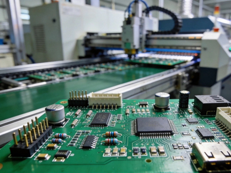
Mixed Assembly Explained: Combining SMT and THT on One PCB in ChinaSeptember/01/2026
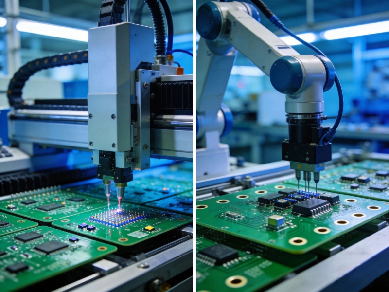
SMT vs THT PCB Assembly in China: Which Technology is Right for Your Project?June/08/2026
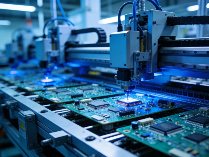
Cost Comparison: SMT vs THT PCB Assembly Services in ChinaJuly/07/2026
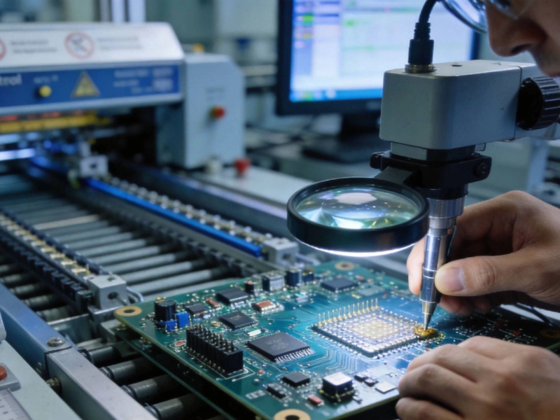
Why IPC Class 3 Standards Matter for Industrial SMT PCB Assembly in ChinaJuly/08/2026