Fiducial marks represent one of the most critical yet often overlooked elements in printed circuit board design for Surface Mount Technology (SMT) assembly. These precision alignment reference points enable pick-and-place machines to accurately position components with micron-level precision. For companies outsourcing Pcb Assembly to China—where high-volume, high-mix production environments demand exceptional accuracy—proper fiducial mark design and placement can mean the difference between smooth, reliable assembly and costly rework or scrap.
While fiducial marks seem simple—typically circular copper features—their implementation requires careful consideration of geometry, placement, and manufacturing constraints. This comprehensive guide explores best practices for fiducial mark design and placement, with specific guidance for optimizing results with Chinese Smt Assembly partners who operate with diverse equipment and varying quality systems.

Understanding Fiducial Marks
What Are Fiducial Marks?
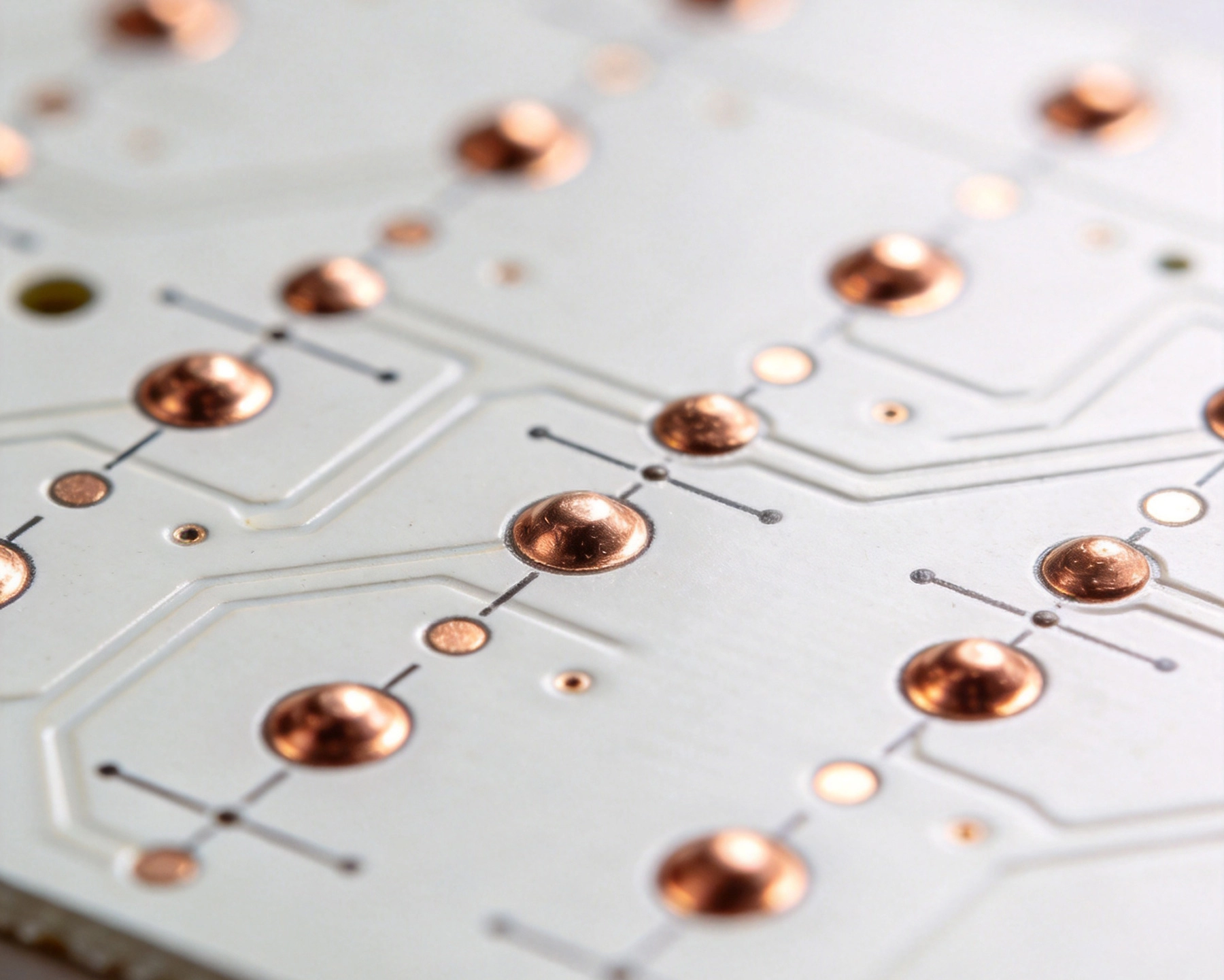
Fiducial marks (also called fiducials or fiducial points) are precision reference features on a PCB that provide visual alignment points for automated assembly equipment. SMT pick-and-place machines use camera systems to locate these marks, calculating the exact position and rotation of the PCB to compensate for any dimensional variations or placement errors.
Fiducials serve several critical functions:
-
Global alignment – Defining the overall board coordinate system
-
Component placement correction – Compensating for panel positioning variations
-
Rotation compensation – Correcting for panel angular misalignment
-
Scale correction – Adjusting for dimensional scaling errors
Types of Fiducial Marks
Fiducials are classified by their scope and location:
-
Global fiducials – Located on the panel edges or corners, providing overall board alignment
-
Local fiducials – Positioned near fine-pitch components, providing enhanced accuracy for critical placements
-
Tooling holes – Mechanical alignment points that sometimes serve dual purposes
Most boards require both global and local fiducials for optimal assembly accuracy.
Global Fiducial Mark Design
Geometry and Dimensions
Industry-standard fiducial geometry follows established best practices:
-
Shape – Circular shape is universally supported by all vision systems
-
Typical diameter – 1.0 mm to 1.5 mm for most applications
-
Minimum diameter – 0.8 mm for high-density designs
-
Maximum diameter – 3.0 mm (larger fiducials don't provide additional benefit)
Square or rectangular fiducials can be used but may not be supported by all equipment. Circular shapes are universally recommended for compatibility.
Background Clearance
Clearance around the fiducial is critical for reliable recognition:
-
Clear area – Unobstructed copper-free area around the fiducial
-
Clearance radius – Equal to or greater than fiducial radius
-
Background material – Consistent solder mask color for optimal contrast
-
No features – No traces, vias, or other copper in the clear area
Proper clearance ensures the vision system can clearly distinguish the fiducial from surrounding features.
Solder Mask Considerations
Solder mask treatment affects fiducial visibility:
-
Exposed copper – Best practice: fiducial exposed, solder mask opening larger than fiducial
-
Solder mask covered – Possible but may reduce contrast and recognition reliability
-
Contrast – Copper should provide clear contrast against solder mask
-
Consistency – All fiducials should have identical treatment
Most manufacturers recommend exposed copper fiducials for optimal machine recognition.
Global Fiducial Placement
Panel-Level Placement
Global fiducials are typically placed at the panel level:
-
Corner placement – Two or three fiducials at panel corners
-
Diagonal placement – Maximum separation for best angular accuracy
-
Edge distance – 5-10 mm from panel edge to avoid handling damage
-
Tooling hole proximity – Often placed near tooling holes for convenience
Three fiducials provide better accuracy than two, but most systems work well with two properly positioned marks.
Board-Level Placement
When individual boards are assembled rather than panels:
-
Opposite corners – Maximum diagonal separation
-
远离边缘 – 2-3 mm from board edges to prevent damage
-
Symmetric placement – Mirror positions for consistent processing
-
Accessible locations – Areas not obstructed by components
Local Fiducial Mark Design
When to Use Local Fiducials
Local fiducials enhance accuracy for critical components:
-
Fine-pitch components – Components with ≤0.5 mm pitch
-
High-density BGAs – BGA packages with Fine Pitch balls
-
QFN packages – Quad Flat No-lead components with hidden connections
-
Precision applications – Any component requiring ±0.05 mm or better placement accuracy
Not all components need local fiducials—focus on those where placement accuracy is critical.
Local Fiducial Placement
Optimal local fiducial positioning:
-
Proximity – 5-10 mm from the target component
-
Unobstructed view – No components between fiducial and placement machine camera
-
Consistent orientation – Same relative position for similar components
-
Multiple fiducials – For large components, consider two local fiducials
Design for Chinese SMT Assembly Considerations
Equipment Compatibility
Chinese assembly facilities use diverse equipment:
-
Universal design – Follow Ipc Standards for broad compatibility
-
Multiple machine types – Design for both entry-level and advanced equipment
-
Legacy system support – Some facilities use older equipment requiring larger fiducials
-
Vision system variation – Different cameras may have varying recognition capabilities
Using standard, conservative design practices ensures compatibility across diverse equipment bases.
Manufacturing Process Considerations
Chinese manufacturing processes may influence fiducial design:
-
Panel handling – Robust placement to survive automated handling
-
Solder mask tolerances – Accommodating standard Chinese fabrication tolerances
-
Dimensional accuracy – Accounting for typical Chinese PCB Fabrication precision
-
Quality system variations – Design that works with different quality standards
Fiducial Mark Placement Best Practices
Number and Distribution
Determining optimal fiducial count:
-
Minimum requirement – Two global fiducials for basic assembly
-
Recommended – Three global fiducials for enhanced accuracy
-
Large panels – Additional fiducials for very large panels (>300mm)
-
Multi-board panels – Global panel fiducials plus individual board fiducials
Spacing and Separation
Proper fiducial spacing maximizes accuracy:
-
Maximum separation – Place fiducials as far apart as practical
-
Diagonal placement – Corner positions provide best angular correction
-
Triangular arrangement – Three fiducials in triangular formation provide optimal reference
-
Even distribution – For multiple fiducials, distribute evenly across the board
Layer Considerations
Fiducial mark implementation across layers:
-
Top and bottom – Fiducials on both sides for double-sided assembly
-
Inner layers – Not typically required for Smt Assembly
-
Consistent placement – Mirror positions on top and bottom layers
-
Through-hole vs. surface – Fiducials are typically surface features, not through-holes
Common Design Mistakes to Avoid
Placement Errors
Common fiducial placement mistakes:
-
Too close to edge – Risk of damage during handling
-
Too close together – Reduces angular accuracy
-
Obstructed by components – Machine camera cannot access fiducial
-
Asymmetric placement – Inconsistent relative positions
Design Flaws
Technical design errors:
-
Insufficient clearance – Traces or vias too close to fiducial
-
Inconsistent sizing – Different fiducial diameters on the same board
-
Poor contrast – Solder mask color insufficient contrast with copper
-
Non-standard shapes – Using shapes not universally supported
Documentation Issues
Communication problems with manufacturers:
-
Undefined in design files – Fiducials not clearly marked in fabrication drawings
-
No specifications provided – Size and placement requirements not documented
-
Ambiguous requirements – Unclear instructions for solder mask treatment
-
Missing from Bom – Fiducial requirements not communicated to assembly partner
Advanced Fiducial Techniques
Enhanced Recognition Features
Improving fiducial recognition reliability:
-
Anti-reflective coating – Matte finish to reduce glare
-
High-contrast background – Dark solder mask with bright copper fiducials
-
Multiple sizes – Different sized fiducials for different purposes
-
Code marks – Adding identifying features for advanced systems
Automated Optical Recognition
Modern vision system capabilities:
-
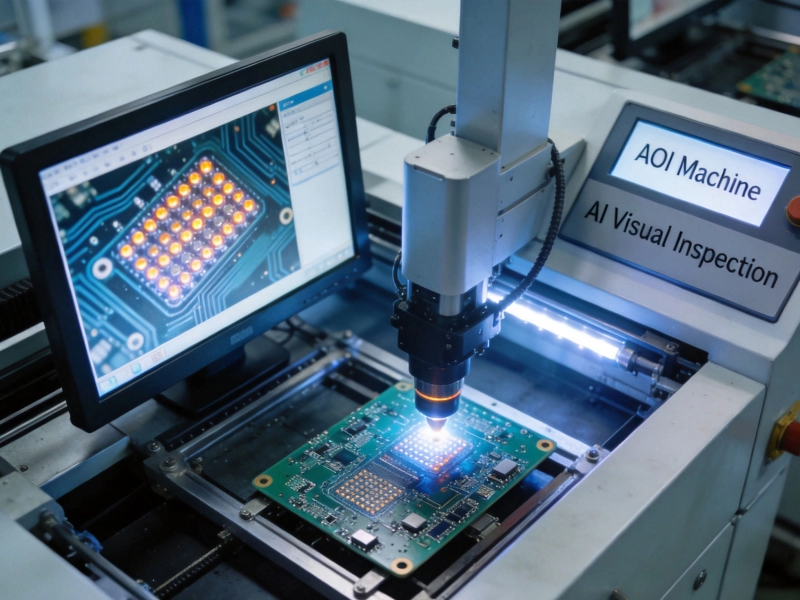
Pattern recognition – Advanced algorithms that can recognize fiducials with partial obstruction
-
Sub-pixel accuracy – Position measurement beyond pixel resolution
-
Multiple fiducial types – Systems that can handle various fiducial geometries
-
Adaptive recognition – Learning algorithms for improved accuracy
Quality Control and Verification
Pre-Assembly Verification
Ensuring fiducials are properly fabricated:
-
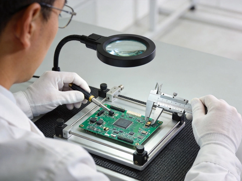
Visual inspection – Checking for proper fabrication and clarity
-
Dimensional verification – Confirming fiducial dimensions match specifications
-
Clearance verification – Ensuring adequate surrounding clearance
-
Contrast measurement – Verifying adequate visual contrast
Assembly Performance Monitoring
Tracking fiducial-related assembly issues:
-
Placement accuracy data – Monitoring component placement accuracy
-
Recognition reliability – Tracking fiducial recognition success rate
-
Alignment correction data – Measuring how much correction is applied
-
Yield analysis – Correlating fiducial issues with placement defects
Standards and Specifications
IPC Standards for Fiducials
Industry standards provide guidance:
-
Ipc-7351 – Generic requirements for Surface Mount design and land pattern standards
-
IPC-2221 – Generic standard on printed board design
-
IPC-7351B – Land Pattern Design standards including fiducial requirements
Following Ipc Standards ensures compatibility with most assembly equipment worldwide, including Chinese manufacturers.
Manufacturer-Specific Requirements
Some assembly partners have specific preferences:
-
Preferred fiducial size – Specific diameter recommendations
-
Placement guidelines – Company-specific positioning requirements
-
Solder mask treatment – Preferences for exposed or covered fiducials
-
Clearance specifications – Company-specific clearance requirements
Always consult with your assembly partner for their specific fiducial requirements.
Design for Assembly Collaboration
Early Communication with Chinese Partners
Effective collaboration prevents issues:
-
Share design requirements – Provide complete fiducial specifications upfront
-
Request feedback – Ask for recommendations based on their equipment
-
Confirm understanding – Verify they understand your fiducial requirements
-
Establish expectations – Define quality criteria for fiducial recognition
Documentation Requirements
Complete documentation ensures success:
-
Fabrication drawings – Clearly marked fiducial locations and specifications
-
Assembly drawings – Fiducial placement and treatment specifications
-
Gerber Files – Accurate representation of fiducial features
-
Bill of Materials notes – Any special fiducial requirements or considerations
Cost and Complexity Considerations
Fiducial-Related Costs
Understanding cost impacts:
-
Board space – Fiducials consume usable board area
-
Design complexity – Additional features require design attention
-
Manufacturing considerations – May affect panelization efficiency
-
Assembly setup – May require additional programming time
These costs are minimal compared to the benefits of improved placement accuracy.
Cost-Benefit Analysis
Weighing fiducial investment against benefits:
-
Reduced rework – Better accuracy reduces placement errors
-
Improved yield – Fewer defective assemblies
-
Faster setup – Better fiducials reduce machine setup time
-
Enhanced reliability – Accurate placement improves long-term reliability
Conclusion
Fiducial marks represent a small but critical investment in SMT PCB Assembly quality and reliability. Proper fiducial design and placement—following established industry standards and considering the specific capabilities of your Chinese assembly partners—enables high-precision component placement that meets the demanding requirements of modern electronic products.
For companies outsourcing Pcb Assembly to China, attention to fiducial details pays dividends through improved first-pass yields, reduced rework costs, and enhanced product reliability. By implementing the best practices outlined in this guide and maintaining open communication with manufacturing partners, designers can ensure that their boards assemble accurately and consistently, regardless of the specific equipment or processes used.
As component densities continue increasing and placement tolerances become tighter, the importance of proper fiducial design will only grow. Establishing robust fiducial practices today positions companies for success with increasingly complex assemblies in the future.
Expert SMT PCB Assembly Services in China
Our Chinese manufacturing facility provides precise SMT assembly with advanced fiducial recognition systems. We work closely with you to ensure your designs translate into reliable, high-quality assemblies. Contact us to discuss your PCB assembly requirements.
Frequently Asked Questions
How many fiducial marks do I need on my PCB?
Minimum requirement is two global fiducials for basic assembly, but three provide better accuracy. Add local fiducials near fine-pitch components (≤0.5mm pitch) or BGAs for enhanced placement precision.
What is the ideal size for fiducial marks?
Standard practice is 1.0-1.5 mm diameter circular fiducials with clearance area equal to or greater than the fiducial radius. Smaller boards may use 0.8 mm minimum, while larger boards can use up to 3 mm (larger provides no additional benefit).
Should fiducials be exposed copper or covered with solder mask?
Exposed copper is the recommended best practice for optimal machine recognition and contrast. Solder mask-covered fiducials may work but can reduce recognition reliability, especially with varying solder mask colors.
How close can fiducials be placed to board edges?
Place fiducials 5-10 mm from panel edges or 2-3 mm from individual board edges to prevent damage during handling and ensure machine cameras can access them reliably.
Do I need local fiducials for every fine-pitch component?
No, only critical components requiring ±0.05 mm or better placement accuracy need local fiducials. Focus on BGAs, QFNs, and components with ≤0.5 mm pitch. Standard 0.65mm pitch components typically work well with global fiducials alone.