
Ball Grid Array (BGA) components have become ubiquitous in modern Electronics Manufacturing, offering superior thermal performance and pin density compared to older package types. However, the hidden solder connections that make BGA packages so effective also create inspection challenges that traditional optical methods cannot resolve. In China's highly competitive Smt Assembly industry, manufacturers who invest in X-ray inspection capabilities distinguish themselves through superior Quality Assurance and reduced field failure rates. Understanding why X-ray inspection is essential for Bga Assembly helps buyers evaluate supplier quality systems and protects end products from reliability problems that emerge in the field.

BGA components mount directly to the PCB surface with solder balls arranged in a grid pattern beneath the package body. Unlike gull-wing or J-lead packages where connections are visible from the side, BGA solder joints hide completely under the component body. This concealment provides manufacturing advantages including shorter signal paths and better thermal dissipation, but it eliminates the visual access that inspectors rely on for traditional solder joint evaluation.
The solder ball array beneath a BGA can contain dozens to thousands of individual connections depending on package size. A mid-range BGA with 25 by 25 ball array contains 625 solder joints that must all form properly for the component to function. With connections this numerous and inaccessible, statistical probability alone guarantees that some joints will have defects in any high-volume production run. Without X-ray inspection, these hidden defects escape detection until field failures create customer complaints and warranty costs.
Thermal expansion mismatch between the BGA package, solder, and PCB creates mechanical stress that can crack solder joints over time. These cracks often do not manifest as immediate opens but as intermittent electrical failures that are extremely difficult to diagnose. BGA joints that pass functional test at room temperature may fail when thermal cycling causes cracked joints to lose contact. X-ray inspection identifies the voids, cracks, and irregularities that predict these field failures.
X-ray inspection systems penetrate the BGA package body to reveal internal solder joint structure. The technology relies on differential X-ray absorption by materials of different densities. Copper traces, solder, and FR4 substrate absorb X-rays differently, creating contrast in the image that reveals internal features. Solder voids appear as darker regions within the joint, while cracks create linear discontinuities that interrupt the uniform solder structure.
Two-dimensional radiography provides projection images similar to medical X-rays. While 2D inspection detects many defect types, overlapping features can hide defects that lie in different planes. Three-dimensional computed tomography (CT) reconstruction creates slice images at arbitrary orientations, revealing defects that 2D inspection cannot detect. CT inspection takes longer and costs more but provides the most thorough evaluation for critical applications.
Automated X-ray inspection (AXI) systems combine X-ray imaging with automated defect recognition software. These systems can inspect 100 percent of BGA joints on production boards at speeds compatible with assembly line throughput. Pattern recognition algorithms compare each joint against established reference images, flagging deviations that exceed tolerance thresholds for operator review.
AXI systems achieve inspection speeds of several boards per minute depending on board complexity and inspection parameters. This throughput enables integration into production lines rather than relegating X-ray inspection to sampling-based quality verification. Real-time inspection catches defects as they occur, enabling immediate process adjustments that prevent defective boards from continuing through assembly.
Void percentage represents one of the most critical BGA inspection metrics. Voids are gas pockets within solder joints that form during reflow when trapped moisture or flux residues vaporize. Industry standards typically limit void percentage to 25 percent or less of the joint cross-sectional area, though more stringent limits apply for critical applications. Voids weaken joints mechanically and create hot spots that accelerate failure under thermal cycling.
Off-center balls, missing balls, and bridging between adjacent joints represent additional defect categories that X-ray inspection readily detects. Solder wicking that draws material away from joints creates opens or high-resistance connections. Insufficient solder from poor paste printing or incomplete reflow leaves weak joints prone to mechanical failure. Each defect type produces recognizable signatures that experienced operators learn to identify.
Every new Bga Assembly program should begin with comprehensive first article inspection that establishes baseline quality expectations. X-ray evaluation of initial production boards reveals process capability before volume production begins. This early detection prevents expensive rework or scrap when design or process problems emerge. First article findings guide process optimization that improves yield for subsequent production runs.
First article inspection should include cross-sectional analysis of representative joints alongside X-ray review. Cross-sections provide definitive verification of joint structure that X-ray alone cannot always confirm. The combination of X-ray screening and cross-section confirmation creates confidence that process settings produce the intended joint geometry.
Integrating X-ray inspection into statistical process control enables proactive quality management rather than reactive defect detection. Monitoring void percentages and other metrics over time reveals process drift before it creates excessive defect rates. Control charts tracking inspection results distinguish random variation from systematic problems requiring intervention.
Leading China SMT manufacturers maintain real-time SPC dashboards that aggregate X-ray inspection data across production shifts and equipment. These dashboards enable rapid response to quality excursions and provide evidence of process stability that customers increasingly request. SPC data also supports Continuous Improvement initiatives that reduce defect rates over product lifecycles.
Quality-focused manufacturers retain X-ray inspection records as part of complete manufacturing traceability. These records document inspection parameters, defect counts, and dispositions for each production lot. When field failures occur, historical inspection data helps diagnose whether the failure originated in assembly processes or other lifecycle factors.
Customers increasingly require statistical quality data as part of supplier qualification. X-ray inspection records demonstrating process capability indices above 1.33 for critical metrics satisfy these requirements. The investment in inspection documentation pays returns through reduced qualification cycles and stronger customer relationships built on transparency.
Voids form when gases become trapped during solder reflow. Moisture absorbed into components or board materials vaporizes when exposed to reflow temperatures, creating pressure that forces solder away from the joint center. Flux carrier volatiles similarly create gas pockets when heated. Proper bake-out procedures before assembly and controlled humidity storage prevent the moisture that causes excessive voiding.
Void distribution within joints affects reliability differently depending on location. Voids near the interface between solder and pad create stress concentrations that accelerate crack propagation. Voids distributed throughout the joint bulk have less impact on mechanical strength. X-ray inspection reveals both void percentage and location, enabling assessment of joint quality beyond simple void counting.
Bridging occurs when solder connects adjacent joints that should remain electrically isolated. Insufficient solder paste separation, excessive paste volume, or poor stencil alignment creates bridges that cause functional shorts. BGA packages with fine ball pitch are particularly susceptible to bridging defects that X-ray inspection readily reveals.
Detecting bridges requires imaging at angles that reveal the space between adjacent balls. Some X-ray systems use tilted imaging or computed tomography to expose bridging that straight-on views might miss. Automated recognition algorithms trained on bridge signatures identify these defects reliably in production inspection.
Head-in-pillow defects occur when partial wetting creates a characteristic appearance resembling a pillow with a head resting on it. One surface of the joint wets properly while the other fails to achieve full metallurgical bonding. This defect creates high-resistance connections that may pass initial electrical test but fail under thermal or mechanical stress.
Non-wet defects where solder fails to wet either surface create similar reliability risks. These defects often result from surface contamination, oxidation, or insufficient thermal energy during reflow. X-ray imaging reveals the incomplete fillet formation and irregular joint structure that characterize these defects.
Cracks within solder joints develop from thermal cycling stress and mechanical shock. These cracks often do not create immediate electrical opens but progressively degrade joint integrity over time. X-ray inspection can detect cracks that appear as linear discontinuities within otherwise intact joint structures.
Identifying true cracks requires careful image interpretation because surface features and imaging artifacts can create false indications. Experienced operators learn to distinguish genuine cracks from projection artifacts by examining multiple viewing angles. Training and calibration standards help maintain consistent interpretation quality across inspection personnel.
When evaluating China Smt Assembly partners, inspect their X-ray equipment directly. Modern systems from manufacturers like Nordson Dage, Waygate Technologies, or Scienscope provide reliable inspection capability. Ask about equipment age, maintenance schedules, and calibration verification. Outdated equipment may not provide the resolution or automation needed for efficient high-volume inspection.
Resolution specifications indicate the smallest feature the system can detect. Systems with 1-micrometer resolution can identify micro-defects that lower-resolution equipment misses. For fine-pitch BGA packages with balls spaced 0.5 millimeters apart, resolution of 5 micrometers or better is typically required for reliable defect detection.
X-ray inspection integrated into production flow provides advantages over off-line inspection that samples boards periodically. In-line systems inspect every board without slowing production, catching defects immediately rather than after additional value has been added through subsequent assembly steps. The cost of detecting defects after ICT or functional test far exceeds early detection costs.
Ask about inspection protocols and sampling plans. While 100 percent inspection provides maximum protection, some applications may justify sampling-based approaches that balance inspection cost against defect escape risk. Understanding the manufacturer's inspection strategy helps assess whether it matches your quality requirements.
Equipment capability alone does not guarantee quality inspection. Trained operators who understand defect signatures and system limitations provide the judgment that automated systems cannot fully replicate. Ask about training programs, certification requirements, and ongoing competency verification for inspection personnel.
Industry certifications like Ipc-a-610 include training on solder joint acceptability that complements X-ray interpretation skills. Manufacturers whose inspection personnel hold relevant certifications demonstrate commitment to quality that translates to reliable inspection results.
X-ray inspection systems represent significant capital investment, with automated systems ranging from $100,000 to $500,000 depending on capability. This investment creates pressure on manufacturers to amortize equipment costs across high production volumes. Understanding how your order volume affects inspection economics helps explain pricing differences between suppliers.
Shared inspection equipment used for multiple customers enables smaller manufacturers to offer X-ray capability without full capital burden. These arrangements work when inspection capacity meets customer requirements without excessive waiting. For critical applications, dedicated inspection equipment provides more reliable access and faster turnaround.
The cost of field defects typically far exceeds inspection costs when properly accounted. Warranty repairs, customer returns, reputation damage, and potential liability from field failures create risk that inspection investment mitigates. For products where failure creates safety implications or significant customer impact, the economics of comprehensive inspection are compelling.
Calculating total defect cost requires estimating defect rates, failure costs, and inspection costs under different scenarios. A spreadsheet model comparing inspection alternatives helps justify investment decisions. Most analyses show that inspection costs are recovered many times over when field failure rates decrease even modestly.
Can Aoi replace X-ray inspection for BGA components?
No. Automated Optical Inspection (Aoi) examines surface features visible from above, but BGA solder joints are hidden beneath the component body. AOI can verify Component Placement and detect some paste-related defects, but cannot assess the actual solder joint quality that determines BGA reliability. X-ray or acoustic micro-imaging is required to inspect hidden joints.
What void percentage is acceptable for BGA joints?
Industry standards typically limit void percentage to 25 percent of joint cross-sectional area for most applications. Aerospace and automotive applications may specify tighter limits of 15 percent or less. Voids exceeding these limits create reliability risks, particularly when located near the solder-pad interface where stress concentrates.
How does China SMT compare to other regions for BGA assembly quality?
China hosts many world-class SMT facilities with advanced equipment and mature quality systems. The most competitive manufacturers invest in latest-generation inspection equipment and maintain rigorous process controls. Quality variation exists across the supplier landscape, making supplier evaluation essential. Top-tier China manufacturers can match or exceed quality from any global competitor.
What sampling plans are appropriate for X-ray inspection?
Sampling plans depend on application criticality and production volume. High-reliability applications may require 100 percent inspection or intensive sampling that approaches full coverage. Consumer Electronics may justify sampling plans based on statistical confidence levels. Ipc Standards provide guidance on sampling approaches appropriate for different quality levels.
How does acoustic micro-imaging compare to X-ray for BGA inspection?
Acoustic micro-imaging (AMI) uses ultrasonic waves to inspect internal structures. AMI can detect delamination and cracks that X-ray misses, but provides less detail on solder microstructure. The two technologies are complementary rather than competitive—many quality programs use both. X-ray remains more common for routine BGA inspection due to wider availability and faster inspection speeds.
X-ray inspection has become indispensable for BGA assembly Quality Assurance in China's SMT industry. The hidden nature of BGA solder joints makes visual inspection impossible, leaving X-ray as the primary tool for detecting the defects that compromise reliability. Manufacturers who invest in X-ray capability demonstrate commitment to quality that protects their customers from field failures and associated costs.
Evaluating SMT partners requires understanding their X-ray inspection capabilities, protocols, and quality track records. Equipment specifications, operator training, and process integration all contribute to effective defect detection. The investment in thorough supplier evaluation pays returns through improved product reliability and reduced lifecycle costs.
As BGA packages continue evolving toward finer pitch and smaller ball sizes, inspection requirements become more demanding. Manufacturers who stay ahead of technology trends by investing in advanced inspection capabilities position themselves to serve demanding applications in automotive, medical, and aerospace markets. X-ray inspection capability has transitioned from optional enhancement to essential requirement for quality-focused BGA assembly.

Step-by-Step: From Solder Paste Printing to Final Testing in China SMT AssemblyJuly/13/2026
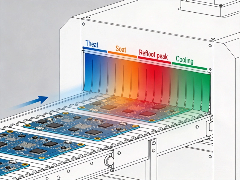
Understanding Reflow Soldering Profiles Used in SMT PCB Assembly ChinaJune/30/2026
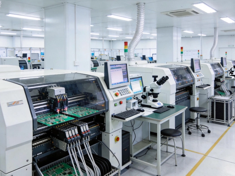
The Complete Process WalkthroughMay/29/2026
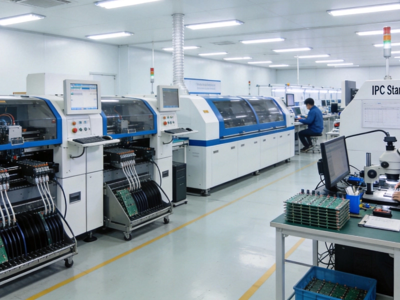
How China's SMT PCB Assembly Process Meets International IPC-A-610 StandardsJuly/22/2026
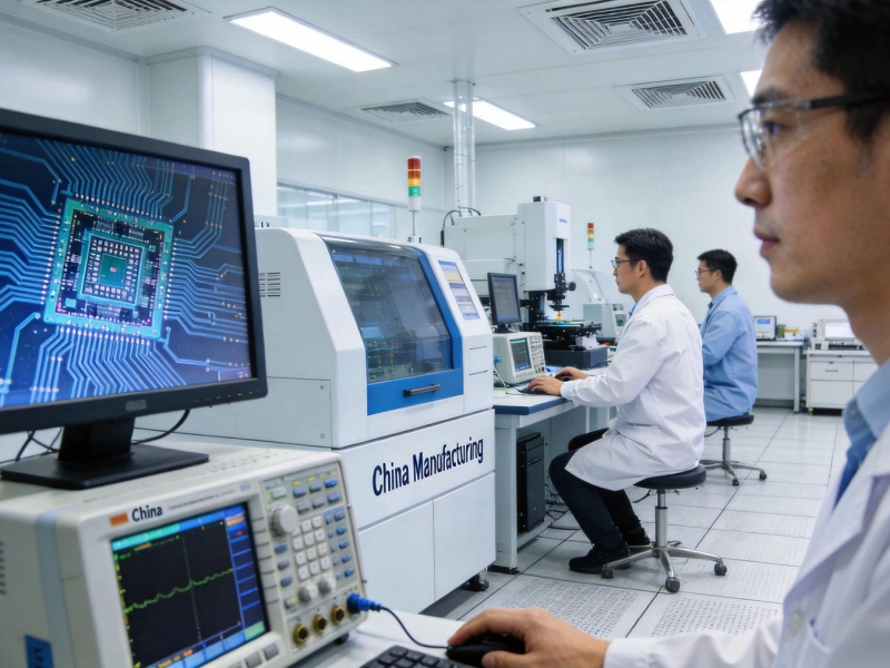
How a Top High Frequency PCB Manufacturer Ensures Signal IntegrityJune/02/2026

How to Place Fiducial Marks for Accurate SMT PCB Assembly in ChinaAugust/15/2026

The Role of Automated Optical Inspection (AOI) in China's SMT Assembly LinesJune/16/2026

Wave Soldering vs. Reflow: Navigating the SMT PCB Assembly Process in ChinaAugust/12/2026