
Printed circuit board design rules differ fundamentally between Surface Mount Technology and Through-hole Technology, yet many engineers treat them interchangeably when preparing designs for Chinese Contract Manufacturers. This oversight creates manufacturing complications that range from unnecessary cost adders to assembly failures requiring complete redesign. Understanding the distinct layout requirements for each technology enables designers to create boards that manufacturers can produce efficiently and reliably. The design decisions made on the drafting table directly determine production outcomes, component costs, and Time-to-market schedules when working with assembly partners in China.

Surface Mount Technology attaches components directly to the PCB surface using solder paste and reflow heating. Components have metal terminations that sit on pads without requiring holes through the board. This approach enables placement on both sides of the board, dramatically higher component density, and automated assembly with minimal human intervention. Chinese Smt Assembly lines achieve placement rates exceeding 50,000 components per hour with accuracy measured in microns.
Through-hole Technology inserts component leads through holes in the board and solders them on the opposite side, typically using Wave Soldering or selective soldering. The mechanical connection provided by through-hole leads offers superior reliability under mechanical stress, making this technology preferred for connectors, heavy components, and applications requiring robust interconnects. However, through-hole components occupy significantly more board space and require drilling holes that add fabrication cost.
SMT dominates modern Electronics Manufacturing, accounting for over 80 percent of component placements globally. Consumer Electronics, mobile devices, computers, and most industrial controls rely almost entirely on Surface Mount technology. The Miniaturization enabled by SMT makes possible the pocket-sized devices that define contemporary electronics. When designing for high volume production, SMT should be the default choice unless specific requirements mandate otherwise.
THT remains essential for applications requiring mechanical robustness, high current capacity, or field replaceability. Automotive under-hood electronics, industrial motor controls, power supplies, and military systems frequently use through-hole construction for connector reliability and serviceability. Audio equipment often benefits from through-hole capacitors and resistors where mechanical stability affects performance. When mixed-technology boards combine both approaches, the design must accommodate the more restrictive requirements of each.
Component Placement in Smt Assembly follows systematic rules that maximize placement efficiency and minimize defects. The orientation, spacing, and grouping of components directly affect pick-and-place programming time, cycle time, and first-pass yield. Designers who understand these considerations create layouts that manufacturers can assemble with minimal adjustment.
Component orientation should follow a consistent pattern, typically with all resistors, capacitors, and inductors oriented with their markings reading in the same direction. This consistency allows placement heads to approach components from predictable angles, reducing programming complexity and improving placement speed. Standard orientation also facilitates visual inspection, making defects easier to identify during quality control.
SMT component spacing depends on component size, placement accuracy, and inspection requirements. Standard spacing guidelines recommend at least 1.0mm between adjacent 0402 components and 0.5mm between adjacent 0201 Components. Fine-pitch devices like 0.4mm BGAs require specific clearance based on the assembly capability of the chosen manufacturer.
The distance between different component types also matters for assembly processing. Large components near small components create height differences that affect Solder Paste Printing and reflow. Shadowing effects where larger components block radiant heat from reaching nearby small parts can cause cold joints. Maintaining minimum clearances around large components prevents these thermal issues.
Logical component grouping reduces setup time and improves placement efficiency. Related components should be placed in proximity, with passive components clustered near their associated active devices. This arrangement shortens signal routing distances while enabling efficient feeder arrangement on the placement machine.
Many manufacturers prefer placing all components of similar size on the same panel location before moving to different sized parts. This sequencing reduces feeder changes and nozzle swaps that slow placement. Designers can support this by grouping similar components rather than spreading them across the board. The resulting placement sequence works efficiently while still routing optimally on the completed board.
Through-hole Component Placement focuses on mechanical accessibility and solder process requirements rather than pure density optimization. The need to insert leads through holes, apply flux, and solder from the bottom surface creates constraints that differ fundamentally from Surface Mount assembly. Proper placement ensures reliable solder joints without bridging, icicles, or incomplete solder fill.
Component lead spacing, called pitch, determines the minimum hole spacing and affects solder wave contact time. Standard pitch components like 0.1-inch headers and 0.2-inch DIP packages follow industry-standard grids that Wave Soldering equipment accommodates easily. Non-standard pitches may require custom tooling or selective soldering, adding cost and complexity to the assembly.
Through-hole design begins with proper hole sizing relative to component leads. The hole must accommodate the lead with adequate clearance for solder penetration while providing sufficient annular ring for reliable connections. Standard practice calls for hole diameter approximately 0.15-0.25mm larger than the maximum lead diameter. For example, a component with 0.5mm diameter leads requires holes of approximately 0.7mm diameter.
Pad diameter must provide adequate annular ring after drilling registration tolerances. Industry standard requires minimum annular ring of 0.15mm for Class 2 reliability and 0.2mm for Class 3. This requirement means that a 0.7mm hole needs a minimum pad diameter of 1.0mm, with larger pads preferred for mechanical robustness. Designers must balance pad size against routing density when through-hole components occupy densely packed areas.
Wave soldering requires adequate clearance from board edges and other features that would interfere with solder contact. The solder wave contacts the bottom of the board as it passes through, requiring that all solderable surfaces be exposed to this contact. Components, mounting holes, and non-soldered features must be positioned away from board edges to prevent solder bridging or incomplete fill.
Standard clearance from board edges to the nearest component lead is typically 3mm minimum, with larger clearances recommended for wave heights exceeding 15mm. Fiducial Marks, tooling holes, and panel cutouts must maintain similar clearances to prevent solder contamination of non-soldered features.
Mixed-technology boards containing both SMT and THT components present Thermal Management challenges during assembly. The reflow process for surface mount components subjects through-hole parts to elevated temperatures before wave soldering completes their connection. Components not designed for reflow exposure may be damaged if their thermal limits are exceeded during surface mount processing.
Thermal profiling for mixed boards must account for the most sensitive component on each side of the assembly. Components rated for multiple reflow passes can be placed on the second side and experience two thermal cycles. Components rated for single reflow must be placed on the first side to avoid repeated exposure. Component datasheets specify reflow ratings that guide placement decisions.
Component height variations create thermal shadowing during reflow processing. Tall components block radiant heat from reaching adjacent shorter parts, potentially creating cold joints. In mixed boards, placing tall components downstream in the reflow direction minimizes shadowing effects on critical joints.
The reflow oven profile can compensate for some shadowing through adjusted heating rates, but design solutions work better than process compensation. Avoiding placement of tall components directly adjacent to thermally sensitive devices prevents shadowing at its source. Heat spreaders and thermal reliefs on ground planes also affect temperature uniformity during processing.
Through-hole pads connected to large copper planes require thermal relief connections to ensure adequate solder heating. Without thermal relief, the heat sinking effect of the plane prevents sufficient temperature rise for reliable solder wetting. The gap between the pad and plane allows localized heating while maintaining electrical connection after soldering.
Thermal relief spoke count and width affect the balance between thermal isolation and mechanical strength. Four spokes provide adequate relief for most applications, while six or eight spokes offer improved heating for very large planes. Spoke width should be minimized to maximize thermal isolation while maintaining structural integrity.
Vias affect both SMT and THT assemblies but in different ways. In surface mount boards, vias that penetrate pads can cause solder wicking that reduces joint volume. Through-hole boards require vias positioned away from hole barrels to prevent solder wicking or contamination of plated-through holes.
Via-in-pad design places vias directly in component pads, enabling higher routing density but creating solder joint risks. Solder can wick down through-holes, reducing fillet size and weakening the joint. Tenting covers vias with solder mask to prevent wicking, while filling uses conductive or non-conductive material to seal the via before component placement.
Through-hole vias connect all layers and provide connection points for component leads in standard Through-hole Assembly. These vias are typically 0.3-0.8mm diameter depending on current capacity and routing requirements. The barrel provides electrical connection through the board while the plating provides solderability for through-hole components.
Blind vias connect outer layers to inner layers without penetrating the full board thickness. These vias enable higher routing density by allowing connections in surface layers without consuming space in inner layers. Buried vias connect only inner layers, further maximizing routing flexibility. Both blind and buried vias add manufacturing cost compared to through-hole vias, so their use should be justified by routing requirements.
Pad design fundamentally affects assembly yield and field reliability. Oversized pads create tombstoning risk as solder surface tension pulls components upright during reflow. Undersized pads reduce joint reliability and may cause components to shift during placement. Proper pad sizing balances these concerns based on component type, board density, and manufacturing capability.
Land pattern standards from IPC provide starting points for pad design based on component type and package style. These standards derive from industry experience and manufacturer capability surveys, offering reliable guidance for most applications. Custom pad modifications may improve yield for specific combinations of component type, board material, and assembly process.
Rectangular pads for resistors and capacitors should extend slightly beyond the component termination in the length direction while maintaining adequate width for the termination contact. The component body overhangs the pad ends slightly, allowing visual inspection of joint quality from the side. Standard overhang is approximately 0.1mm minimum, allowing solder fillet visibility without excessive exposure.
Thermal pads for Power Components require special consideration. These large pads may not release solder paste effectively during printing. Window pane patterns, metal webbing, or solder mask dams help control solder volume while maintaining thermal connection. The specific thermal pad design should be coordinated with the assembly manufacturer for optimal results.
Through-hole pads are typically circular, sized to provide adequate annular ring after drilling and plating registration variations. The pad should be round without thermal reliefs that would reduce the solderable surface. Thermal relief connects the pad to planes after the connection point rather than as part of the pad itself.
Plated-over-hole (POH) technology places a solder mask opening over the barrel of a through-hole, allowing surface mount solder to seal the hole without wave soldering. This approach enables mixed-technology assembly without the thermal exposure of wave soldering. POH requires careful process control to achieve reliable seals, so coordination with the manufacturer is essential for success.
Solder mask defines the solderable areas of the PCB while protecting copper traces from oxidation and contamination. In SMT assembly, the mask prevents solder bridging between adjacent pads during reflow. In Tht Assembly, mask controls where solder from wave or selective processes can flow, preventing shorts to adjacent traces.
Solder mask openings must be accurately registered to underlying pads. Registration errors that expose copper beyond the pad create unintended solderable surfaces that may bridge to adjacent components. Registration errors that cover pad corners reduce the effective pad size, potentially causing insufficient solder joints. Standard mask tolerance is typically ±0.05mm from pad edge.
Silkscreen markings provide reference designators, polarity indicators, and assembly orientation guides. These markings help assembly operators correctly place components and assist in troubleshooting during testing and repair. Clear, accurate silkscreen reduces assembly errors and accelerates inspection.
Component polarity markings are essential for polarized components including electrolytic capacitors, diodes, and ICs. Pin one indicators, cathode bars, and orientation dots help ensure correct placement during assembly. The silkscreen should clearly indicate polarity when the component marking may be obscured after placement.
Testability affects how easily assembled boards can be verified for correct assembly and functionality. Designs that ignore testability may require expensive test fixtures, experience longer test times, or fail to detect defects that manifest in customer use. Incorporating test points and accessibility features supports efficient quality verification.
Through-hole boards offer inherent test accessibility as component leads extend through the board and can be probed from the bottom. SMT boards require dedicated test points positioned for probe access. Via test points should be placed away from components to allow probe landing without interference.
In-circuit testing uses bed-of-nails fixtures to contact test points throughout the board. Each test point requires a minimum pad size and clearance from surrounding features. Standard ICT pad sizes are typically 0.8-1.0mm diameter, with 2.0mm minimum spacing from board edges and 1.0mm from other test points.
Flying probe testing uses roving probes to contact test points without dedicated fixtures. This approach suits lower-volume production and prototype quantities where fixture cost is prohibitive. Flying probe requires larger test points, typically 1.0-1.2mm diameter, and wider spacing to accommodate probe accuracy limitations.
Functional test requires access points for power, communication, and signal measurement. Test points should be clearly marked with consistent labeling that identifies their function. Connector access may suffice for boards with communication interfaces, while boundary scan testing can verify JTAG-compatible devices without physical probe access.
Test point placement should consider the test jig or fixture interface. Edge connectors or test connectors provide convenient access points that support both ICT and functional test. Programming connectors for flash memory or microcontrollers should be positioned for easy fixture connection during test.
Chinese Contract Manufacturers produce PCBs in manufacturing panels that maximize utilization of standard panel sizes. Design decisions about board shape, mounting hole placement, and array configuration affect how efficiently panels can be populated and assembled. Designers who understand panel efficiency can reduce per-unit costs without compromising design requirements.
Panel utilization describes the percentage of panel area containing productive boards versus tooling and waste areas. Higher utilization reduces per-board material cost and often reduces per-board handling cost as well. Boards with complex shapes or unusual dimensions may waste substantial panel area, increasing cost.
V-scoring creates partially cut grooves along panel borders that allow boards to snap apart after assembly. This approach provides clean edges without additional machining but requires adequate clearance from board features to prevent damage during depanelization. Standard clearance from V-score to the nearest component or trace is 1.0mm minimum.
Tab Routing uses tabs to connect individual boards to the panel frame during assembly. The tabs are typically 3-5mm wide and positioned to support the board during handling without stressing components. Breakaway tabs create small notches at the board edge that are usually acceptable for finished product appearance.
Depanelization stress can damage components, particularly those near board edges or mounting holes. V-scoring concentrates stress at the score line, which may propagate toward nearby components if the score is positioned too close. Tab Routing distributes stress through the tabs, potentially creating less localized stress concentration.
Components positioned within 3mm of board edges face elevated risk from depanelization stress. If placement near edges is necessary, additional support features or breakaway tabs can protect sensitive components. The assembly manufacturer should be consulted for specific recommendations based on their depanelization methods.
Successful manufacturing outcomes depend on clear communication between designers and assembly partners. Incomplete documentation, ambiguous specifications, and unclear requirements create manufacturing delays and potential quality issues. Providing comprehensive documentation in standard formats enables manufacturers to process orders efficiently and identify potential problems early.
Gerber Files should include all copper layers, solder mask layers, silkscreen layers, and drill files in standard formats. These files should be clearly labeled with layer names and revision identifiers that match other documentation. Readme files or specification sheets should describe any special requirements or processing notes.
The Bill of Materials must be complete, accurate, and unambiguous for efficient assembly processing. Each component line should include manufacturer part number, quantity per board, reference designators, and any special sourcing requirements. Preferred parts lists help manufacturers substitute equivalent components when primary sources are unavailable.
Alternative parts should be pre-qualified to ensure they meet design requirements. The time required to qualify substitutes after an order is placed can delay production significantly. Proactive Bom management that identifies potential shortages and qualifies alternatives before they become critical improves delivery reliability.
Assembly drawings supplement the Bom with visual guidance for component placement, orientation, and special requirements. These drawings should clearly indicate component positions using reference designators matched to the BOM. Orientation requirements for polarized components should be explicitly indicated with pin one locations clearly marked.
Special processing instructions address non-standard requirements that may not be obvious from standard manufacturing processes. Conformal Coating areas, potting requirements, test specifications, and packing instructions all require explicit documentation. The more specific and complete these instructions are, the more likely the manufacturer will meet expectations without requiring clarification.
Designers new to working with Chinese contract manufacturers often encounter preventable issues that delay production or increase costs. Understanding these common pitfalls helps designers avoid them in their own projects. The most frequent issues relate to tolerance assumptions, documentation completeness, and communication clarity.
Tolerance stack-up errors occur when design tolerances do not account for accumulated manufacturing variations. A design with tight tolerances may be manufacturable in prototype quantities but fail production yields when statistical variation increases defect rates. Designing to achievable tolerances rather than theoretical minimums improves first-pass yield.
Version control failures cause confusion when multiple revisions of documentation exist. A manufacturing run may proceed with outdated Gerber Files while the BOM reflects newer requirements, creating mismatches that require rework. Consistent revision numbering across all documentation, with explicit change logs, prevents this confusion.
Clear file naming conventions should include revision identifiers that match across all deliverables. ZIP or RAR archives should contain only files matching the stated revision to prevent accidental mixing of old and new documentation. The manufacturer should be notified when revisions occur, even minor ones, to ensure production uses current specifications.
Working with Chinese manufacturers across time zone differences requires planning for communication delays. Questions submitted late in the Chinese workday may not receive responses until the following day. Beginning new design projects with clear specifications reduces the need for extensive communication during production.
English documentation is standard for most Chinese contract manufacturers serving international markets, but technical terminology may not translate precisely. Clarifying ambiguous terms and providing visual references where language might cause confusion improves mutual understanding. Cultural differences in directness may also affect communication style, requiring flexibility in interpreting responses.
Design rules for SMT and Tht Assembly differ substantially, requiring designers to understand both technologies when creating boards for Chinese contract manufacturers. Surface mount technology demands precise pad design, component spacing, and placement optimization for high-speed assembly efficiency. Through-hole technology focuses on hole sizing, annular ring requirements, and wave solder process compatibility.
Mixed-technology boards must accommodate the more restrictive requirements of each approach while managing thermal interactions between reflow and wave soldering processes. Design for testability ensures that completed boards can be efficiently verified for correct assembly and function. Panel design and documentation practices affect manufacturing efficiency and cost across production volumes.
The investment in understanding these design rules pays returns through smoother production runs, higher first-pass yields, and faster Time-to-market. Collaboration with Chinese assembly partners during the design phase identifies potential issues while design changes are inexpensive. The combination of knowledgeable designers and capable manufacturing partners creates products that meet quality, cost, and delivery objectives.

Cost Comparison: SMT vs THT PCB Assembly Services in ChinaJuly/07/2026
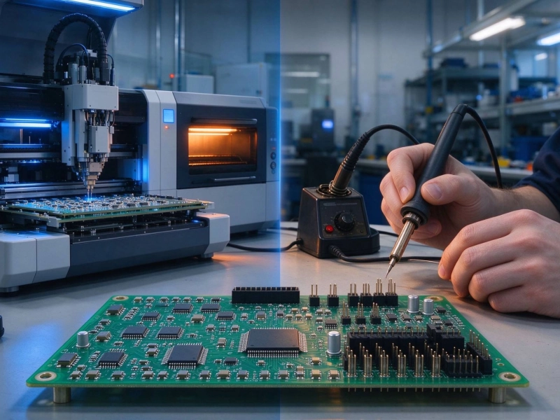
How to Choose the Best Assembly Method for Your PCB Prototype in ChinaOctober/12/2026
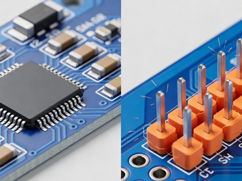
Understanding the Mechanical Strength Differences: SMT vs THT Assembly in ChinaJuly/27/2026

The Evolution of Electronics in China: From THT to High-Density SMT PCB AssemblyAugust/06/2026

Automation Capabilities: Why SMT Assembly Wins Over THT for Mass Production in ChinaSeptember/10/2026

The Pros and Cons of SMT and THT in China's Electronics Manufacturing LandscapeJune/25/2026
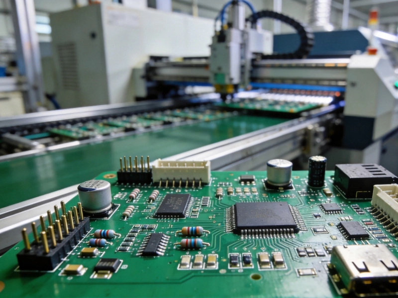
Mixed Assembly Explained: Combining SMT and THT on One PCB in ChinaSeptember/01/2026
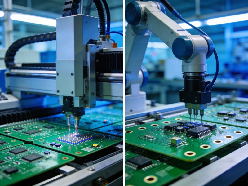
SMT vs THT PCB Assembly in China: Which Technology is Right for Your Project?June/08/2026