Mixed-technology printed circuit boards that combine Through-hole Technology (THT) and Surface Mount Technology (SMT) remain essential in modern Electronics Manufacturing. Despite the industry-wide shift toward Surface Mount components, through-hole parts continue to serve critical functions in power delivery, mechanical mounting, and legacy compatibility. Designing boards that successfully integrate both technologies requires careful consideration of assembly sequencing, Component Placement, and manufacturing flow, especially when producing in China where assembly facilities have specific expertise in mixed-technology production.
This guide provides comprehensive guidance for engineers designing mixed-technology boards for China-based manufacturing. Understanding the nuances of integrating THT and Smt Assembly helps prevent production delays, reduces costs, and ensures consistent quality across production runs.

Understanding Mixed-Technology Assembly
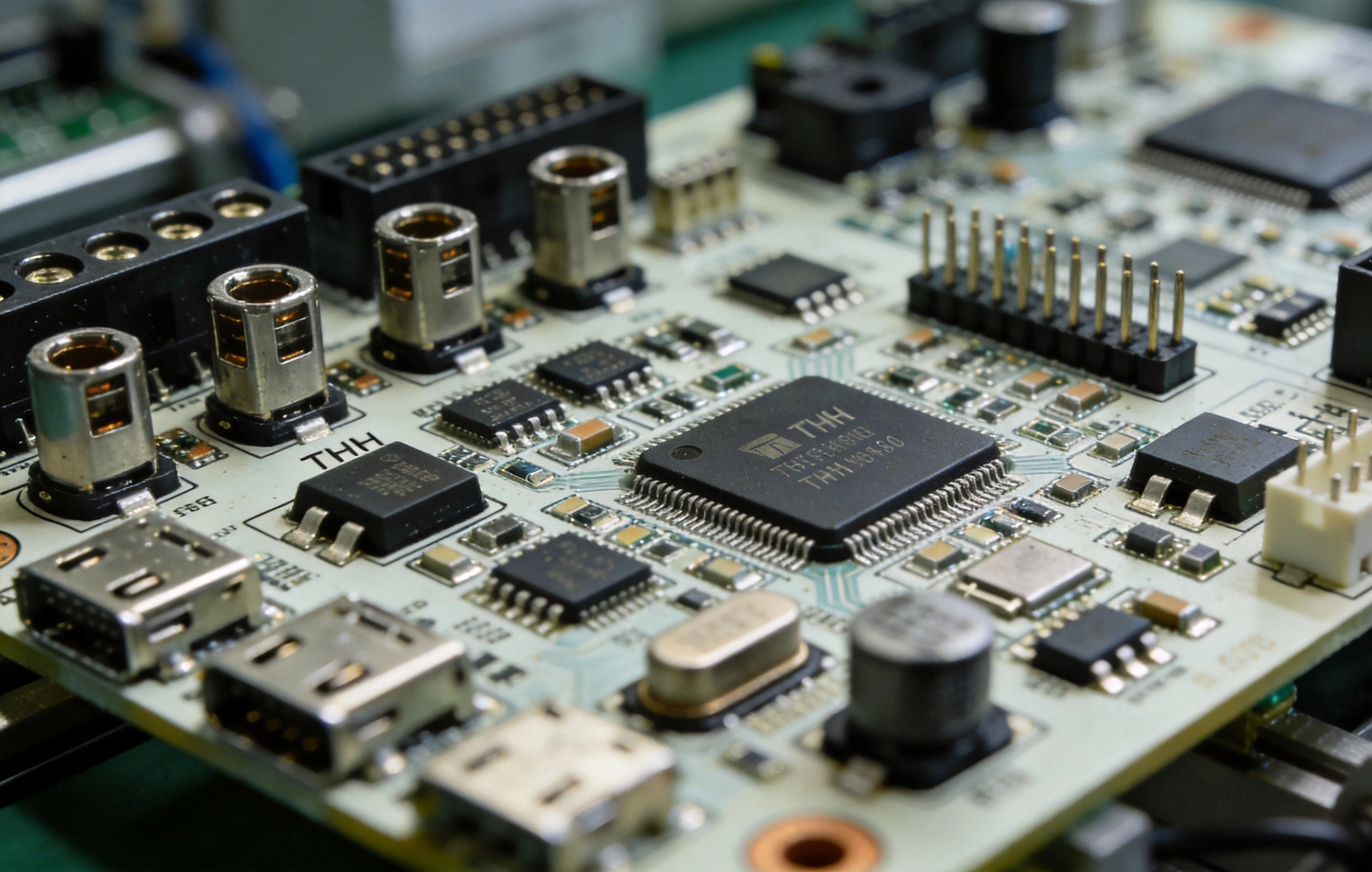
Mixed-technology assemblies combine components attached using different methods on the same PCB. Each technology brings specific advantages that designers leverage for optimal board performance and manufacturing efficiency.
Surface Mount Technology Advantages
SMT has become the dominant assembly technology for good reason:
- Higher component density enables smaller boards
- Automated placement achieves faster throughput
- Components mount on both sides of the board
- Better high-frequency electrical performance
- Lower manufacturing cost for standard components
Through-Hole Technology Advantages
THT remains irreplaceable for specific applications:
- Superior mechanical connection for connectors and stress points
- Better heat dissipation for power components
- Easier manual repair and component replacement
- Required for certain connector types and pin arrays
- Preferred for components subject to frequent removal
Assembly Process Flow
The sequence in which components are assembled significantly impacts manufacturing success and should guide design decisions.
Standard Process Sequence
The typical assembly sequence for mixed-technology boards follows this order:
- Step 1: Apply solder paste to SMT pads for first side
- Step 2: Place SMT components on first side
- Step 3: Reflow solder paste for first-side SMT
- Step 4: Flip board and apply solder paste for second side
- Step 5: Place SMT components on second side
- Step 6: Reflow solder paste for second-side SMT
- Step 7: Insert THT components
- Step 8: Wave solder or selective solder THT components
- Step 9: Clean, inspect, and test
Alternative Sequences
Alternative sequences exist for specific requirements:
- Hand solder THT first: For heat-sensitive second-side components
- Sequential selective soldering: For complex mixed assemblies
- Post-assembly THT insertion: For extremely heat-sensitive components
Design Guidelines for Manufacturability
Design decisions fundamentally impact assembly success. Following established Dfm Guidelines prevents production problems.
Component Placement Strategy
Strategic Component Placement facilitates efficient assembly:
- Group THT components in accessible areas away from dense SMT zones
- Place heat-sensitive components away from wave solder exposure areas
- Provide clearance between SMT and THT for solder containment
- Consider assembly flow when positioning components
Pad Design Considerations
Through-hole pad design affects solder joint reliability:
- Maintain adequate annular ring around drilled holes
- Specify appropriate pad finish for your application
- Consider thermal relief for connections to ground planes
- Verify pad size matches component lead diameter
Board Edge Considerations
Edge effects require specific attention in mixed assemblies:
- Keep SMT components at least 3mm from panel edges
- Position THT connectors away from wave solder rail contact areas
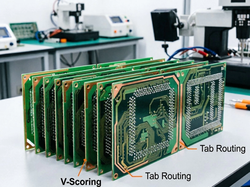
- Include panelization features for manufacturing handling
- Account for depanelization effects near edge components
Thermal Management in Mixed Assemblies
Thermal considerations differ between THT and SMT and require integrated planning.
Reflow Thermal Exposure
THT components experience multiple thermal cycles during Mixed Assembly:
- First-side SMT reflow exposes entire board to peak temperature
- Second-side reflow repeats thermal exposure
- Wave solder adds additional thermal stress
- Components must tolerate cumulative thermal exposure
Heat-Sensitive Component Handling
Some components require special consideration:
- Electrolytic capacitors have temperature limits
- Plastic connectors may warp at reflow temperatures
- Some connectors require hand soldering to avoid damage
- Verify MSL ratings for all components
Power Component Placement
Power components combining THT and SMT require thermal planning:
- Place thermal pads on accessible board areas
- Consider heat sink mounting provisions
- Route thermal vias appropriately for heat dissipation
- Balance SMT and THT power components strategically
China Manufacturing Considerations
Producing mixed-technology boards in China offers advantages but requires understanding local manufacturing practices.
Facility Capability Assessment
When selecting a China manufacturer for mixed assemblies, evaluate:
- Wave Soldering capability and equipment condition
- Selective soldering availability for complex assemblies
- Component sourcing support for THT parts
- Quality inspection processes for both technologies
Communication and Documentation
Clear communication prevents Manufacturing Errors:
- Provide complete assembly drawings with clear notation
- Specify assembly sequence explicitly if non-standard
- Include first-article inspection requirements
- Document any hand-soldering operations
Component Sourcing Strategy
THT component sourcing differs from SMT:
- Some THT parts may require longer lead times
- Minimum order quantities may differ from SMT reels
- Verify manufacturer can source specified THT components
- Consider alternate THT sources for common parts
Quality Control Approaches
Quality control for mixed assemblies encompasses both THT and SMT inspection requirements.
SMT Inspection Points
Standard SMT inspection applies to surface components:
THT Inspection Points
Through-hole inspection includes additional considerations:
- Visual inspection of solder fillet formation
- Cross-section analysis for critical joints
- Pull testing for mechanical verification
- Connector seating verification
Test Coverage Planning
Test strategy should cover both technologies:
- ICT for electrical verification of all nodes
- Functional testing for completed assemblies
- Boundary scan for complex components
- In-circuit testing for power circuits
Common Design Mistakes
Understanding common mistakes helps designers avoid them.
Component Conflict Issues
Frequent conflicts arise from poor planning:
- Placing THT components where wave solder cannot reach
- Mounting heat-sensitive components in wave solder zones
- Overlapping THT and SMT pad areas without clearance
- Forgetting to specify assembly sequence for complex boards
Thermal Damage Problems
Thermal issues frequently cause failures:
- Exceeding component temperature ratings during assembly
- Not accounting for multiple thermal exposures
- Placing solder-sensitive components near heat sources
- Ignoring moisture sensitivity requirements
Manufacturing Hand-Off Issues
Documentation problems cause delays:
- Missing assembly sequence specifications
- Unclear component orientation markings
- Ambiguous special instruction handling
- Incomplete bill of materials for THT parts
Process Optimization Techniques
Optimizing the manufacturing process improves quality and reduces cost.
Design for Wave Soldering
Wave solder success depends on design decisions:
- Maintain minimum 2mm clearance between SMT and THT areas
- Route traces perpendicular to wave direction in solder zones
- Provide adequate pad spacing for solder bridge prevention
- Consider solder mask dams between closely spaced THT pads
Selective Soldering Applications
Selective soldering solves many wave solder limitations:
- Process heat-sensitive areas individually
- Handle mixed technology without compromising SMT
- Reduce flux contamination concerns
- Improve yield for complex assemblies
Hybrid Assembly Strategies
Advanced boards may require multiple processes:
- Combine wave and selective soldering on same board
- Include hand-soldering operations for specific components
- Plan post-assembly operations in production flow
- Document all non-standard processes
Cost Optimization
Understanding cost drivers helps optimize design decisions.
Component Cost Considerations
Component selection affects total cost:
- THT components generally cost more than SMT equivalents
- Some THT parts have minimum order quantity requirements
- Hand-soldered THT operations increase labor cost
- Alternative components may reduce cost significantly
Assembly Cost Factors
Manufacturing costs vary with design:
- More THT insertions increase assembly time
- Selective soldering costs more than standard wave
- Complex sequences may require additional handling
- Hand operations add significant labor cost
Test Cost Optimization
Test costs depend on design choices:
- Accessible test points reduce ICT setup cost
- Boundary scan reduces physical test requirements
- Design for testability reduces overall test cost
- Consider test coverage vs. cost trade-offs
Summary: Key Takeaways
Successful mixed-technology board design requires integrated thinking:
- Plan assembly sequence early: Design decisions must support the intended assembly flow
- Consider thermal exposure: Components must tolerate cumulative thermal cycles
- Provide clearance: Separate THT and SMT zones appropriately
- Specify clearly: Document assembly sequence and special requirements
- Evaluate manufacturer capability: Verify equipment matches your requirements
- Optimize for cost: Balance component and assembly costs throughout design
Mixed-technology boards will remain essential for foreseeable future electronics. Designing them successfully requires understanding both technologies and how they interact during manufacturing. Early planning prevents production problems and ensures consistent quality across production runs.
Frequently Asked Questions
What is the typical assembly sequence for mixed THT and SMT boards?
The standard sequence places and reflows SMT components first, typically in two stages for double-sided boards, followed by THT component insertion and wave or selective soldering. This sequence protects SMT components from the thermal exposure of Wave Soldering.
How do I handle heat-sensitive THT components?
For components that cannot survive wave soldering temperatures, consider hand soldering after wave processing, using selective soldering for those specific components, selecting alternative SMT components if possible, or using sockets that allow later component installation.
What clearance is needed between THT and SMT components?
Maintain minimum 2mm clearance between through-hole component leads and nearby Surface Mount pads. This clearance prevents solder splash from contaminating SMT joints during wave soldering and ensures adequate access for inspection and repair.
Can all THT components go through reflow soldering?
Most THT components are not rated for Reflow Soldering due to their construction. Only certain chip-type components and leadless packages designed for reflow can tolerate reflow profiles. Standard through-hole components with leads require wave or hand soldering.
How does mixed technology affect manufacturing cost?
Mixed-technology assemblies typically cost more than pure SMT due to additional processing steps including THT insertion, wave or selective soldering, and potentially hand operations. However, the benefits of THT components often justify the additional cost for mechanical robustness and thermal performance.
What should I include in documentation for China manufacturing?
Include complete assembly drawings showing both technologies, explicit assembly sequence instructions, component orientation markings, any special handling requirements, complete bill of materials with THT parts distinguished, and first-article inspection requirements.