Open Nav

China's Pcb Assembly industry has matured dramatically over the past decade. The image of the low-cost, low-quality offshore assembler is increasingly outdated—at least for the tier-one factories that serve industrial, automotive, and medical OEMs. These facilities have invested heavily in automated inspection equipment, process control systems, and quality management certifications that match or approach the standards of the best Western assemblers. But quality is not automatic—it is the result of specific, well-defined protocols implemented consistently across the production process.
Understanding the quality control protocols that govern industrial Smt Assembly in Chinese factories is essential for OEMs who source from China. This knowledge enables you to evaluate potential partners intelligently, specify your quality requirements precisely, and verify that the protocols are actually implemented—not just documented in a quality manual that sits on a shelf.
Before examining specific protocols, it is important to understand the quality framework within which they operate.
Every serious Pcb Assembly factory in China holds ISO 9001 certification. This is the minimum acceptable credential—it demonstrates that the factory operates a documented quality management system. However, ISO 9001 alone says nothing about the technical capability to assemble industrial-class boards. It is a necessary but insufficient condition.
For factories serving the automotive industry, Iatf 16949 certification is required. This standard extends ISO 9001 with automotive-specific requirements including advanced product quality planning (APQP), production part approval process (PPAP), failure mode and effects analysis (FMEA), measurement systems analysis (MSA), and statistical process control (SPC). Iatf 16949-certified factories have process control systems that go well beyond ISO 9001 and are generally capable of meeting the most demanding industrial quality requirements.
Factories assembling PCBs for medical devices must hold Iso 13485 certification. This standard adds requirements for design controls (if the factory performs any design activity), process validation, risk management per ISO 14971, and Traceability. Medical Device Assembly requires the most rigorous documentation and process control of any non-aerospace application.
While not a certification per se, Ipc-a-610 "Acceptability of Electronic Assemblies" defines the visual acceptability criteria for solder joints, Component Placement, and board cleanliness. The factory must specify which Ipc-a-610 class they build to as their default, and you must specify which class your product requires. For industrial applications, Class 2 is typical; for safety-critical applications (automotive ADAS, medical devices, railway signaling), Class 3 is required. The difference between Class 2 and Class 3 is significant—it affects minimum solder volume, maximum void size, placement accuracy, and cleanliness requirements, all of which drive process parameters and inspection criteria.
Quality begins before any component is placed. The incoming material control protocols prevent defective materials from entering the production process.
Before a bare PCB enters the assembly line, the factory performs incoming inspection. For industrial-class assembly, this typically includes:
For automotive and medical applications, incoming inspection may also include electrical test verification—confirming that the board's netlist matches the design data by checking a sample against the electrical test report from the bare board fabricator.
Component quality control protocols vary by application criticality:
Solder paste is a perishable material whose properties directly affect joint quality. Incoming and ongoing controls include:
The most effective quality control occurs during the process—not after it. In-process protocols catch defects at the earliest possible stage, when rework is cheapest and the root cause is easiest to identify.
3D SPI is the first and arguably most valuable in-process inspection step. After Solder Paste Printing, the SPI system measures the volume, height, and area of every paste deposit on the board. Key protocol elements include:
In tier-one Chinese factories serving industrial OEMs, SPI is standard equipment. If a factory does not offer SPI, this is a significant quality capability gap for industrial applications.
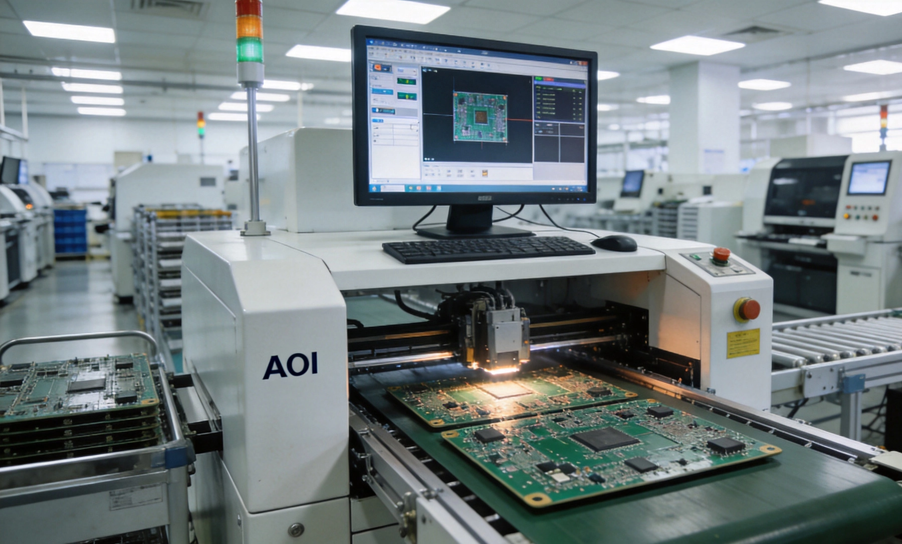
After Component Placement and before reflow, Aoi verifies that components are correctly positioned:
Pre-reflow AOI is particularly valuable for detecting placement errors that would be difficult or impossible to correct after reflow—polarity reversals on electrolytic capacitors, for example, can cause catastrophic failures that post-reflow inspection may not detect if the capacitor has not yet failed.
The reflow oven's thermal profile is the most critical process parameter for solder joint quality. Protocols include:
After reflow, AOI inspects the board for solder joint quality and component integrity:
The AOI program must be developed and validated for each board design. Program development includes algorithm selection, lighting configuration, and pass/fail threshold optimization. The critical metric for AOI program quality is the false call rate—the percentage of flagged defects that are actually acceptable. A high false call rate wastes operator review time and erodes confidence in the inspection system. Tier-one factories target false call rates below 5% for post-reflow AOI.
BGA and QFN solder joints are hidden beneath the component body, invisible to optical inspection. X-ray Inspection protocols include:
After assembly, additional quality control steps verify overall board functionality and cleanliness.
Electrical testing verifies that the board is correctly assembled and functional:
FCT powers up the board and verifies that it performs its intended function. For industrial PCBs, FCT typically includes:
For industrial boards that operate in harsh environments, ionic cleanliness testing verifies that flux residues and other ionic contaminants are below acceptable limits:
Before full production begins, First Article Inspection (FAI) provides the most important quality gate of the entire production run. FAI verifies that the process—equipment, programs, materials, and parameters—is correctly set up and producing conforming product.
Production does not proceed until FAI is approved. If FAI reveals defects, the root cause is identified and corrected, and new first articles are produced and inspected. This gate prevents a process problem from affecting the entire production run.
Industrial and Automotive Quality requirements demand comprehensive traceability—the ability to trace every finished board back to its constituent materials, process parameters, and the personnel involved in its production.
For each board, the factory records:
This traceability enables targeted recalls if a component lot is later found to be defective—only the boards built with that specific lot are affected, not the entire production run.
Each board is assigned a unique serial number—typically laser-marked as a 2D data matrix code on the board surface. This serial number links all inspection data, test results, and process records for that specific board. In automotive applications, board serialization is mandatory per IATF 16949 traceability requirements.
Beyond inspecting product quality, leading Chinese factories validate and monitor the processes that produce that quality.
For critical process parameters—placement accuracy, solder paste volume, reflow peak temperature—the factory performs capability studies that calculate the Cpk index (process capability ratio). Cpk values above 1.33 indicate a capable process with adequate margin; values below 1.0 indicate that the process is producing out-of-specification results. For automotive applications, Cpk above 1.67 is typically required for safety-critical parameters.
SPC charts track critical process parameters over time, using control limits (typically ±3 sigma) to distinguish normal process variation from assignable causes that require intervention. SPC enables the factory to detect and correct process drift before it produces defects—a proactive quality approach that is far more effective than reactive inspection alone.
In IATF 16949-certified factories, SPC is mandatory for key characteristics. In ISO 9001-only factories, SPC may not be implemented—ask specifically whether SPC is used and for which parameters.
MSA verifies that the measurement systems used for quality decisions—AOI algorithms, SPI volume measurements, CMM dimensional checks—themselves produce accurate and repeatable results. An out-of-calibration AOI system that falsely accepts defective boards is worse than no AOI at all. MSA studies (GR&R—gauge repeatability and reproducibility) are required in IATF 16949 environments and should be requested for critical inspection systems in any application.
Quality is not static—it must continuously improve. The protocols that drive improvement are as important as the inspection protocols that detect defects.
When a quality problem occurs—whether detected internally or reported by a customer—the CAPA system drives root cause analysis and permanent corrective action. An effective CAPA system:
When evaluating a Chinese assembly partner, ask for examples of CAPA reports. The quality of the root cause analysis and the permanence of the corrective actions reveal the true quality culture of the factory.
Tier-one factories track first-pass yield (the percentage of boards passing all inspections without rework) and continuously work to improve it. Yield improvement initiatives include:
Quality manuals and capability presentations are easy to create. Verifying that protocols are actually followed on the production floor requires more effort.
Visit the factory. Walk the production line. Observe the inspection stations—does the SPI machine exist and is it being used, or is it covered with a dust cloth? Are AOI results being reviewed by operators, or are boards being passed without review? Is the reflow profile being checked at the specified intervals? Nothing substitutes for seeing the process in action.
Request recent quality records: SPI data, AOI defect rates, first-pass yield data, customer return rates, CAPA reports. A factory that is proud of its quality will share this data readily. A factory that is reluctant may have something to hide.
For automotive and medical applications, third-party audits are standard. Certification bodies audit IATF 16949 and ISO 13485 compliance annually. You can also commission your own process audit—either through a qualified third-party auditing firm or by sending your own quality engineers to the factory.
The quality control protocols that govern industrial SMT PCB Assembly in Chinese factories have evolved significantly. The best facilities implement comprehensive, multi-layered quality systems—incoming inspection, in-process monitoring (SPI, AOI, X-ray), post-assembly test (ICT, FCT), first article gates, traceability, process validation (SPC, MSA), and Continuous Improvement (CAPA)—that match the requirements of demanding industrial, automotive, and medical applications.
But quality capability varies widely across the Chinese assembly industry. The tier-one factories that serve global OEMs have invested in the equipment, training, and quality management systems necessary to deliver industrial-class quality consistently. Smaller or less capable factories may have some of the right equipment but lack the process discipline, documentation, and Continuous Improvement culture that transforms equipment capability into product quality.
For OEMs sourcing from China, the key is verification—auditing the factory, reviewing quality records, and confirming that the protocols described in this article are not just documented but actually implemented and consistently followed. The effort invested in verification pays for itself many times over in reduced quality escapes, lower warranty costs, and the confidence that comes from knowing your boards are built right.
High-Mix Low-Volume Success: Flexible SMT Assembly for Industrial Clients in ChinaOctober/13/2026
Why IPC Class 3 Standards Matter for Industrial SMT PCB Assembly in ChinaJuly/08/2026

Ensuring Long-Term Supply Chain Stability for Industrial SMT Assembly in ChinaSeptember/03/2026
The Demands of Industrial SMT PCB Assembly in ChinaMay/29/2026
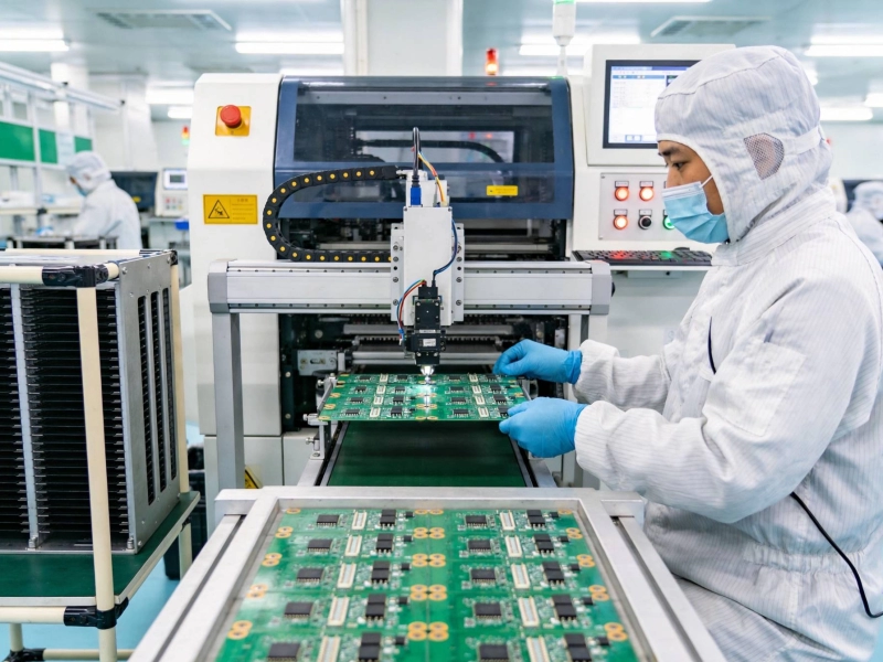
Why IPC Class 3 Standards Matter for Industrial SMT PCB Assembly in ChinaJune/28/2026
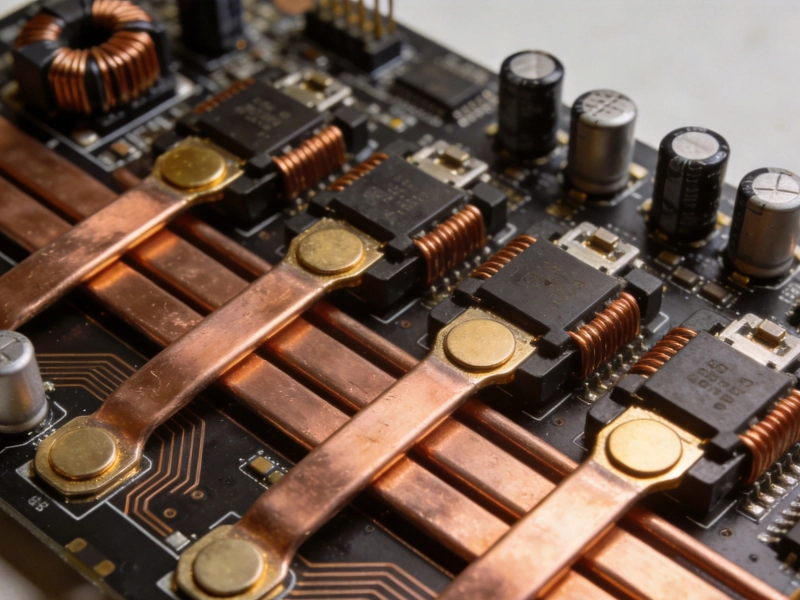
Heavy Copper PCBs and High-Power Components in Industrial SMT Assembly ChinaSeptember/14/2026

SMT PCB Assembly for Harsh Environments: Conformal Coating Solutions in ChinaJuly/18/2026

The Evolution of Electronics in China: From THT to High-Density SMT PCB AssemblyAugust/06/2026