
Surface Mount Technology dominates modern Electronics Assembly, offering automation efficiency, component density, and manufacturing speed that through-hole mounting cannot match. Yet throwing out through-hole components entirely creates problems that pure SMT advocates discover the hard way. Connectors that endure mechanical stress, electrolytic capacitors with specific voltage ratings, and components requiring field replaceability all favor through-hole mounting. Chinese Contract Manufacturers have developed sophisticated mixed-technology assembly capabilities precisely because practical products require both approaches. Understanding when Through-hole Technology adds value alongside SMT determines whether your assemblies achieve optimal cost-performance balance or carry unnecessary expense and reliability risk.
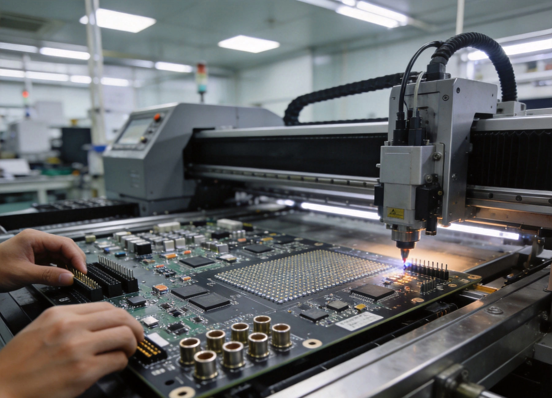
Through-hole Technology earned its place through decades of proven reliability. Component leads pass through holes in the PCB and are soldered to pads on the opposite side, creating robust mechanical connections that resist vibration, thermal cycling, and mechanical stress. While SMT connections rely on solder wetting and component weight for mechanical integrity, through-hole joints contain component leads providing structural support throughout the product lifetime.
Heavy components—connectors, transformers, large electrolytic capacitors—create significant mechanical loads on circuit boards. SMT solder joints resist these loads poorly, potentially cracking under sustained stress or failing during drop events. Through-hole leads distribute mechanical loads across the entire pad-hole interface, tolerating forces that would tear SMT components from boards.
The electronics industry learned these lessons through decades of field failures. Military and aerospace specifications mandate through-hole or equivalent mounting for components subject to vibration and mechanical stress. Automotive Electronics adopted through-hole mounting for similar reasons. Consumer products that survive rough handling similarly benefit from through-hole robustness.
Through-hole leads provide superior thermal paths from components to PCB planes and traces. Power Components dissipating significant heat benefit from through-hole mounting that conducts thermal energy through component leads into thermal vias and copper planes. The continuous metal path from component junction through board interconnect handles heat more effectively than the small solder contact areas of Surface Mount packages.
High-current applications similarly benefit from through-hole current capacity. A through-hole component lead with typical 0.7mm diameter carries more current than the solder-wetted pad area of an equivalent Surface Mount component. Power inductors, current sense resistors, and bus bars frequently use through-hole construction for this current-handling advantage.
Surface Mount Technology offers compelling manufacturing benefits that drive its widespread adoption. Component density, assembly speed, and automated manufacturing efficiency combine to reduce costs dramatically compared to Through-hole Assembly.
Smt Assembly places components automatically at rates exceeding 50,000 components per hour on high-speed lines. Through-hole insertion typically achieves 2,000-5,000 components per hour—ten to twenty times slower. This throughput difference directly impacts manufacturing cost, particularly for high-volume production where assembly labor represents significant expense.
Component costs favor SMT as well. Equivalent surface mount components typically cost less than their through-hole counterparts due to higher production volumes and simpler packaging. Lead-free RoHS compliance is simpler with SMT because through-hole parts require lead-free alloys that are more difficult to process in Wave Soldering.
Surface mount components occupy less board area than through-hole packages with equivalent functionality. The absence of lead holes and annular rings required for through-hole mounting allows denser routing and smaller board sizes. For portable products where Miniaturization drives competitive positioning, SMT's density advantage becomes essential.
Both sides of the PCB become usable assembly surfaces with SMT. Through-hole components typically mount only on the top side, leaving bottom-side assembly available only for SMD components. Mixed-technology boards must plan Component Placement carefully to avoid through-hole components blocking bottom-side assembly.
Mixed-technology assembly combining through-hole and surface mount components addresses application requirements that neither technology handles optimally alone. Chinese Contract Manufacturers have refined hybrid assembly processes to achieve cost and quality outcomes impossible with single-technology approaches.
Connectors requiring frequent mating cycles—USB ports, audio jacks, card readers—need through-hole mounting to survive repeated mechanical stress. SMT mounting these components risks solder joint fractures after relatively few insertion cycles. Design practice places this type of connector in through-hole packages, accepting the assembly cost for the mechanical robustness the application requires.
Electrolytic capacitors maintain cost and availability advantages over ceramic or film alternatives for high-capacitance, high-voltage applications. Aluminum electrolytics commonly use through-hole packages suitable for hybrid assembly. Similarly, large inductors and transformers for power applications ship as through-hole components due to their size and power dissipation requirements.
Products designed for field service benefit from through-hole mounting for components expected to require replacement. Industrial equipment, telecommunications infrastructure, and Automotive Electronics frequently undergo field repairs where technicians must remove and reinstall components. Through-hole solder joints tolerate repeated heating and component removal without board damage that SMT boards may experience.
This consideration extends to components with known failure rates—connectors that wear out, components exposed to lightning surges, replaceable fuses. Through-hole mounting simplifies field repair while SMT mounting for the majority of components preserves manufacturing cost efficiency.
China's Electronics Manufacturing industry developed mixed-technology capabilities serving both domestic and international customers. Understanding these capabilities helps you specify assemblies appropriately and communicate requirements effectively.
h3>Selective Soldering ProcessesModern hybrid assembly rarely uses full Wave Soldering that would reflow surface mount components. Instead, selective solder applicators precisely deposit solder only where through-hole components require it. This process uses nozzles and fixtures protecting surrounding SMD components from solder splash and thermal exposure.
Selective soldering achieves quality levels impossible with wave soldering on boards with mixed technologies. Configurable solder nozzle shapes match specific component footprints, minimizing solder exposure to nearby components. Process control software programs solder patterns, ensuring repeatability across production runs and board revisions.
Some Chinese factories employ through-hole reflow processes for hybrid assembly where all components—including through-hole parts—receive solder in reflow ovens. This approach uses pin-in-paste technology: applying solder paste to through-hole pads before component insertion, then reflowing the entire assembly. This method achieves good solder joint quality but requires careful paste volume calculation and may not suit all component types.
Press-fit technology offers an alternative for high-reliability applications. Press-fit pins engage with plated through-holes through mechanical interference rather than solder. The connection provides excellent mechanical robustness without solder-related reliability concerns. Not all Chinese factories offer press-fit capability, so verify availability for applications requiring this technology.
Low-volume and prototype assemblies frequently use manual through-hole insertion and Hand Soldering. Chinese contract manufacturers maintain skilled workforce for these operations, though volume production benefits from automated insertion where possible. Labor cost advantages in China make manual insertion economically viable for volumes where full automation isn't justified.
Manual soldering becomes necessary for certain through-hole components that automated equipment cannot handle—unusual package sizes, components requiring specific orientation, or boards with limited accessibility. Chinese factory quality control for manual operations must verify solder joint quality through inspection protocols that catch defects human operators might overlook.
Hybrid assembly costs exceed pure SMT production due to additional process steps and slower through-hole insertion speeds. Understanding these cost drivers helps you make appropriate trade-off decisions.
Through-hole insertion adds machine time compared to pure Smt Assembly. Insertion equipment setup and programming for each unique component type adds NRE costs. Selective soldering fixture creation and programming adds setup expenses. These fixed costs amortize across production volume, with higher volumes reducing per-board incremental costs.
Quality inspection for mixed assemblies requires more comprehensive procedures than single-technology boards. X-ray Inspection becomes important for hidden solder joints under connectors and components, adding testing costs that pure SMT boards may not require. Factor these inspection costs into total manufacturing cost estimates.
Below approximately 100 boards, manual through-hole insertion often costs less than setting up automated insertion equipment. The NRE costs of machine setup spread across small volumes make automation economically unattractive. Chinese factories with experienced Manual Assembly workforces can handle these low volumes efficiently.
Above 1,000-5,000 boards depending on component count and assembly complexity, automated through-hole insertion becomes cost-competitive with manual operations. The specific breakpoint depends on through-hole component count, board complexity, and factory-specific labor versus equipment cost ratios.
Successful hybrid assembly starts with design decisions that enable efficient manufacturing. Following established guidelines prevents surprises during production and ensures consistent quality.
Place through-hole components on one side of the board—the side that will encounter selective soldering or wave soldering second. This approach simplifies fixturing and reduces process complexity. If through-hole components must exist on both sides, expect higher manufacturing costs and more complex process control.
Separate through-hole and surface mount components into distinct zones where possible. Dense through-hole component areas simplify selective soldering nozzle design and reduce fixture complexity. Mixing through-hole and SMD components throughout the board increases manufacturing difficulty without offsetting benefits.
Standard through-hole component leads range from 0.5mm to 1.2mm diameter. Standard drill sizes accommodate these leads with appropriate annular ring for reliable plating and solder joints. Avoid oversized holes that complicate solder filling or undersized holes preventing component insertion.
If your design requires non-standard component lead sizes, verify that Chinese factories can accommodate without special tooling charges. Standard drill sizes in 0.05mm increments from 0.3mm to 3.2mm typically incur no tooling costs; non-standard sizes require custom drill bits that add expense and potentially extend lead times.
Ipc Standards specify minimum annular ring requirements for different reliability classes. Class 3 aerospace and medical applications require annular rings of 0.15mm minimum while Class 2 commercial products accept 0.05mm minimum. Specify appropriate annular ring requirements based on your application reliability needs.
Pad diameter must accommodate component lead, solder fillet, and process tolerance stackup. Standard pad designs for common through-hole components—resistors, capacitors, DIP packages—exist for most component families. Unusual components may require custom pad specifications based on lead dimensions and hole size.
Hybrid assemblies require quality verification covering both through-hole and surface mount solder joints, with additional attention to interface areas where both technologies meet.
Visual inspection catches obvious defects—missing components, gross solder bridging, component orientation errors—but cannot verify hidden solder joints. Through-hole solder joints hidden under components require X-ray Inspection or cross-sectioning for complete verification.
Automated Optical Inspection (Aoi) works well for visible SMT joints but has limited capability viewing through-hole joints from the component side. Aoi on the solder side reveals solder fillet formation for through-hole components, providing reasonable quality indication without full X-ray examination.
Functional testing validates assembly performance beyond solder joint integrity. In-circuit testing checks for opens, shorts, and component value verification. Boundary scan testing addresses inaccessible nodes where physical probe access is impossible. Specify testing requirements based on your Quality Assurance needs and defect escape tolerance.
Burn-in testing for high-reliability applications subjects assemblies to elevated temperature and powered operation, accelerating failure mechanisms that would otherwise appear in field operation. This testing adds cost but identifies infant mortality failures before products reach customers.
Through-hole components sometimes face availability challenges different from their surface mount counterparts. Managing component supply ensures Production Continuity.
Through-hole components face ongoing obsolescence as manufacturers discontinue older packages. Some component types—large electrolytics, axial resistors, heavy connectors—retain through-hole packages due to application requirements while market availability narrows. Qualifying alternative sources becomes important when primary sources announce discontinuation.
Chinese contract manufacturers often maintain relationships with component distributors and can assist with obsolescence management. Their visibility across multiple customer programs surfaces availability concerns earlier than single-program buyers might notice.
Through-hole components with long lead times or narrow availability warrant inventory buffering. Chinese manufacturing operations can manage component banking where you purchase and store components for future assembly. This approach guarantees availability while potentially enabling cost savings through volume purchasing.
Work with your Contract Manufacturer to identify critical through-hole components requiring buffer stock. Their production experience identifies components that commonly create supply disruptions and recommend appropriate inventory levels.
Clear communication with Chinese contract manufacturers prevents misunderstandings that compromise hybrid Assembly Quality and cost outcomes.
Document through-hole and surface mount components separately in your Bom, clearly indicating which components require through-hole insertion versus surface mount placement. This separation simplifies factory planning and prevents placement errors where SMT components might be inserted through-hole by mistake.
Provide assembly drawings indicating component locations, orientation requirements, and critical soldering specifications. Through-hole components often have orientation requirements—polarized capacitors, keyed connectors, asymmetric packages—that visual Bom references may not convey clearly.
Before committing to production, qualify the Mixed Assembly process through First Article Inspection. Produce a small number of boards, inspect thoroughly, and verify performance before releasing factory for full production. This qualification catches process capability issues before they affect large production volumes.
Document qualification results and establish acceptance criteria for ongoing production. Ipc Standards provide baseline requirements, but your application may require tighter specifications based on reliability expectations. Communicate these requirements explicitly to manufacturing partners.
Through-hole technology remains essential for specific applications where SMT cannot provide equivalent performance. Connectors enduring mechanical stress, Power Components requiring superior thermal paths, and products designed for field service all benefit from through-hole mounting. Chinese contract manufacturers have developed sophisticated mixed-technology assembly capabilities precisely because practical electronics require both approaches.
The decision to include through-hole components should follow from application requirements rather than historical habit or default selection. Evaluate each through-hole component against SMT alternatives, considering cost, reliability, and manufacturing implications. Where through-hole mounting is justified, work with manufacturers experienced in hybrid assembly to optimize designs and processes.
Hybrid assembly introduces cost and complexity compared to pure SMT production. These additions pay for themselves when through-hole mounting provides genuine performance or reliability benefits. Over-specifying through-hole requirements where SMT alternatives suffice wastes manufacturing resources without offsetting value.
Chinese factories offer capabilities for mixed-technology assembly ranging from prototype volumes through high-volume production. Selecting partners with demonstrated experience in your specific hybrid assembly requirements ensures quality outcomes. Invest time in vendor qualification and process development before production commitment.
Your products will ultimately be judged by their performance and reliability in customer hands, not by manufacturing technology purity. Choose through-hole technology where it serves genuine needs, and embrace SMT for everything else. This pragmatic approach delivers optimal outcomes across cost, quality, and reliability dimensions.
SMT PCB Assembly China Applications for Smart Home and Wearable DevicesSeptember/16/2026
Industrial Control and Automation: Key Applications of SMT PCB Assembly in ChinaAugust/11/2026
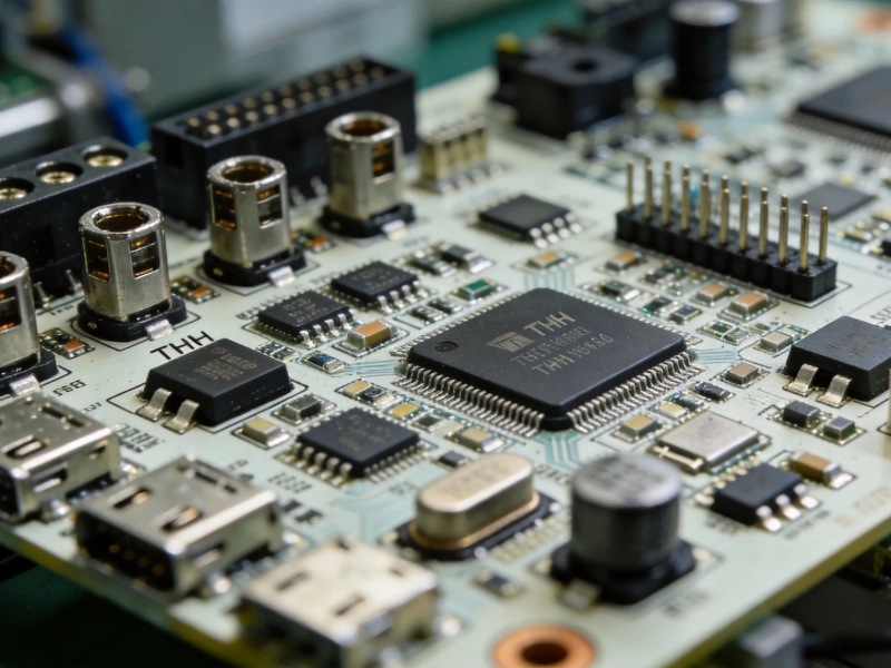
Designing Mixed-Technology Boards: Integrating THT and SMT Assembly for China ProductionSeptember/09/2026
A Deep Dive into a Turnkey SMT PCB Assembly China Project for Consumer ElectronicsOctober/16/2026
PCB Stack-up Considerations for Reliable SMT PCB Assembly in Chinese Supply ChainsSeptember/20/2026
Avoiding Tombstoning: PCB Design Tips for Passive SMT Components in China AssemblyOctober/10/2026

Thermal Management in PCB Design: Preventing Warpage in China's SMT AssemblyJuly/15/2026

Top Applications of SMT PCB Assembly in China: From Automotive to IoTJune/15/2026